AVD-W9000/UR
22
1
2
3
4
1
2
3
4
C
D
F
A
B
E
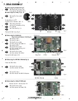
7. DISASSEMBLY
Packing the part of
with the mark is removed. (Fig.1, 2)
1
9WXGA Module
1
Holder
2
3
Holder
FFC
FPC
The entire grill is bent,
and hook is removed pushing
the grille
near the mark.(Fig.1, 2)
2
4
-
Removing the Case (Fig.1, 2)
-
Removing the Bracket (Fig.1)
Case
Bracket
Remove the the Case.(Fig.1)
Remove the five screws.
(Fig.1)
Remove the four screws and
then remove the bracket.(Fig.1)
Fig.1
Fig.2
-
Removing the RGB Unit,
Key Unit and Senser Unit (Fig.3)
Remove the screw.
Remove the FFC1.
Remove the FFC2.
Remove the FFC3.
RGB Unit
FFC1
Key Unit
FFC2
Senser Unit
Remove the the Senser Unit.
Remove the two screws
and then remove the Holder.
Remove the two screws
and then remove the Key Unit.
Remove the two screws
and then remove the RGB Unit.
Cable
-
Removing the 9WXGA Module(Fig.4)
Remove the two screws
and then remove the holder.
Remove the screw
and then remove the 9WXGA Module.
-
Removing the Video PCB(Fig.5)
Remove the five screws
and then remove the Video PCB.
Fig.3
Fig.4
Grille
Remove the FFC. Remove the FPC.
2
1
1
1
1
4
1
1
1
1
1
1
3
4
5
1
1
1
1
2
2
1
2
3
3
4
4
1
1
1
1
1
1
3
5
Disconnect the Cable.
FFC3
Summary of Contents for AVD-W9000
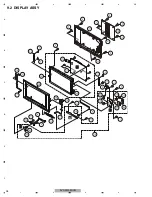
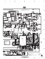
Page 28: ...AVD W9000 UR 28 1 2 3 4 1 2 3 4 C D F A B E 9 2 DISPLAY ASSY B C D E ...
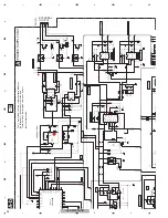
Page 30: ...AVD W9000 UR 30 1 2 3 4 1 2 3 4 C D F A B E 9 3 POWER SUPPLY ASSY A ...
Page 55: ...AVD W9000 UR 55 5 6 7 8 5 6 7 8 C D F A B E ...
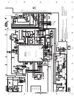
Page 66: ...AVD W9000 UR 66 1 2 3 4 1 2 3 4 C D F A B E E E SERVICE UNIT VIDEO PCB ...
Page 67: ...AVD W9000 UR 67 5 6 7 8 5 6 7 8 C D F A B E E SIDE B ...

