AVD-W9000/UR
8
1
2
3
4
1
2
3
4
C
D
F
A
B
E
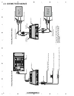
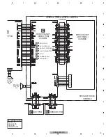
2.3 CONNECTION DIAGRAM
Connecting
the
power
cable
Black (chassis ground)
Connect to a clean
, paint-free metal location
.
F
use resistor
Re
d
Connect to terminal controlled by ignition switch (12 V DC).
F
use (4 A)
Y
ellow
Connect to the constant 12 V supply terminal.
P
ower cable
Display unit
4 m
P
ink
P
ink
Display cable
Hide-away unit
Connecting
with
RCA
cables
External video
component
(sold separately)
Display unit with
RCA input jacks
(sold separately)
Connect to video output
Connect to audio outputs
Connect to video input
Connect to audio inputs
Hide-away unit
Connect with RCA cables
(sold separately)
Connect with RCA cables
(sold separately)
VCR2 IN
(VCR2 input)
VCR1 IN
(VCR1 input)
VCR OUT
(VCR output)
•
The
signal
from
COMPONENT
OUT
(com-
ponent
output)
and
VCR
OUT
(VCR
output)
is
not
output
when
power
to
this
display
unit
is
turned
off
.
Summary of Contents for AVD-W9000
Page 28: ...AVD W9000 UR 28 1 2 3 4 1 2 3 4 C D F A B E 9 2 DISPLAY ASSY B C D E ...
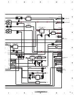
Page 30: ...AVD W9000 UR 30 1 2 3 4 1 2 3 4 C D F A B E 9 3 POWER SUPPLY ASSY A ...
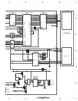
Page 55: ...AVD W9000 UR 55 5 6 7 8 5 6 7 8 C D F A B E ...
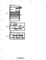
Page 66: ...AVD W9000 UR 66 1 2 3 4 1 2 3 4 C D F A B E E E SERVICE UNIT VIDEO PCB ...
Page 67: ...AVD W9000 UR 67 5 6 7 8 5 6 7 8 C D F A B E E SIDE B ...


