background image

Inspection and Cleaning:

z

Keep batteries clean and dry from residue.

z

Check that all vent caps are tight.

z

Use a solution of baking soda and water to clean if there is acid residue on batteries or corrosion on the terminals.  

DO NOT ALLOW ANY BAKING SODA SOLUTION TO ENTER THE BATTERIES.

z

Terminal protectors, protective spray, or petroleum jelly should be applied to terminals to reduce corrosion.

z

Replace any worn or damaged wires.

Watering:

z

Add distilled water, never acid to cells.

z

DO NOT OVERWATER!

z

Always keep battery caps on, except when adding water or taking hydrometer readings.

z

If the batteries are fully charged, add water to a level of 1/8” below bottom of fill well.

z

If the batteries are discharged, add water to a level just above the plates.

z

After watering, replace and tighten all vent caps.

Storage:

z

Batteries should be fully charged prior to and during storage.

z

Never store discharged batteries.

z

Store batteries in a cool, dry place.

z

Recharge batteries before putting them back into service.

Charge Limits:

z

It is not necessary to charge the batteries if the hydrometry, after a work day, is not under 1.240 (28 Be).

z

The maximum suggested temperature is 113° F (45° C).

z

If the electrolyte temperature exceeds more than 50° F (10° C) above the outside temperature, the batteries can

be overcharged.  

Vacuum Motor Maintenance

The vacuum motors must be checked and cleaned.  The brushes should be checked every six months and replaced if
necessary.

To maintain the vacuum motor, follow these instructions:

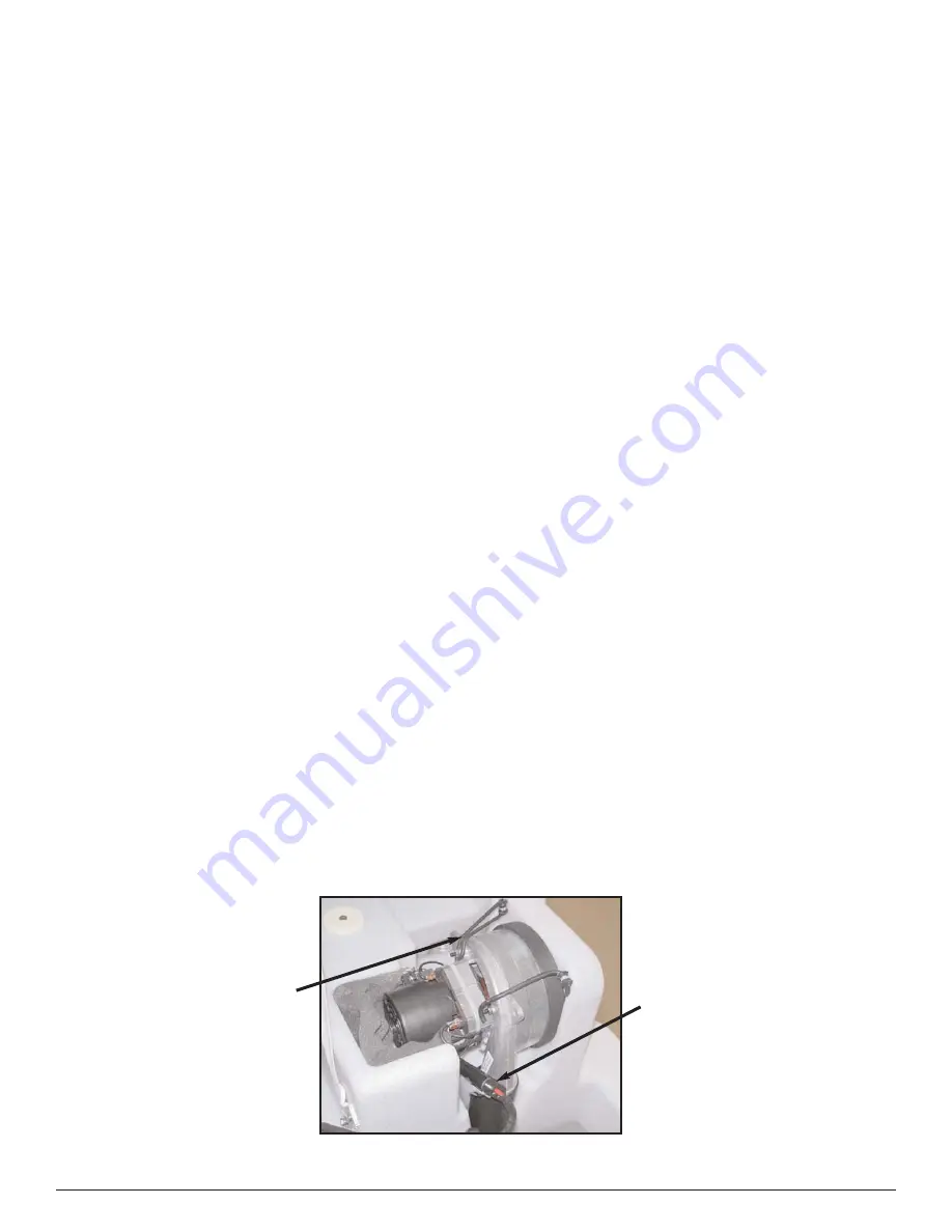
After removing the key from the dashboard, remove the vacuum motor by unhooking the rubber straps and unplug the
connection plug.  Remove the sponge filter under the motor so that it can be cleaned and replaced.  Check the suction
fan from the hole located in the front part of the vacuum motor.  By a visual check, the fan should appear undamaged
and well cleaned.  To check the brushes, first remove the plastic cap, then unscrew the screws and remove the two
plastic brush supports.  Once checked, the brushes can be easily remounted by reassembling all elements.

Connection Plug

16

Rubber Straps

Summary of Contents for CleanStar 30M

Page 1: ...o a resultado en da o a la m quina o propiedad pr xima Cada operador debe ser entrenado en la operaci n de esta m quina antes de ser permitido utilizarla Ponerse en contacto con el servicio de Amano P...

Page 2: ...indicates that the possibility of severe bodily injury or death can occur if DANGER statements are ignored Read and observe all DANGER statements included in the Operation Manual and attached to the m...

Page 3: ...ine 6 Storage 6 Unpacking the Machine 6 Handling the Unpacked Machine 6 Battery Installation 7 Identifying the Machine 8 Machine Operation 9 Controls and Instruments 9 Symbols on the Dashboard 10 How...

Page 4: ...8 000 ft2 hr 4460 m2 hr Noise Level 70 dBA Pads Brushes 2 x 15 in 2 x 38 5 cm Vibration Level Less than 2 5 m s2 Scrubbing Width 29 5 in 75 cm Pad Brush Motor 700W 32A 24V Squeegee Width 37 4 in 95 cm...

Page 5: ...ere burns Do not touch these parts of the machine until they have cooled WARNING Injury can occur to the eyes and body while using the machine Safety goggles safety shoes and safety clothing are recom...

Page 6: ...vironment other than an indoor environment Amano Pioneer Eclipse battery powered floor machines are designed and manufactured for commercial floor maintenance only This machine is designed to scrub mo...

Page 7: ...used without the guards in place Emergency Seat Switch The machine is equipped with a switch under the operators seat Therefore the machine cannot be used without the operator properly seated Warning...

Page 8: ...reason Do not stack the boxes Storage The machine must be stored in an enclosed and dry place if not immediately installed in order to keep every part safe Relative humidity must be lower than 80 and...

Page 9: ...ng the batteries or battery cables wear protective gloves and goggles Avoid contact with battery acid z When charging the batteries raise the solution tank to expose the battery compartment z Install...

Page 10: ...Identifying the Machine Note A silver label has been place on the side of the steering column The label identifies the data referring to the CE marking This label should never be removed 8...

Page 11: ...Machine Operation Controls and Instruments Diagnostic Light Battery Charge Level Indicator Forward Reverse Switch Solution Lever Key Switch Squeegee Raise Lower and Vacuum Motor On Off Lever 9...

Page 12: ...Symbols on the Dashboard 10 l Horn Battery Charge Level Reverse Gear Scrub Brushes Off Scrub Brushes On Diagnostic Light Solution Flow...

Page 13: ...ve the solution valve in the ON position The solution will continue to dispense until the solution control lever is turned to the OFF position It is not turned ON and OFF with the scrub brushes Prepar...

Page 14: ...e Lever This lever will lower the squeegee and also turn the vacuum motor on This lever must be in the raised position before traveling in reverse 1 Steering Pod 2 Acceleration Lever 3 Solution Contro...

Page 15: ...remove the squeegee this may be necessary to pass through a door opening loosen the knobs that retain the squeegee to the machine See item 2 Note Drying may be affected if suction hose is not properly...

Page 16: ...l support and press it upward 5 After replacing the brushes replace the side skirts Be sure they are fully installed before operation Squeegee Blade Replacement Squeegee blades must be replaced when t...

Page 17: ...e Braking System Every 3 Months Trained Technician Check the Battery Cable Connections Weekly Operator Check the Brushes of Each Motor Every Year Trained Technician Check the Safety Devices Every 6 Mo...

Page 18: ...place z Recharge batteries before putting them back into service Charge Limits z It is not necessary to charge the batteries if the hydrometry after a work day is not under 1 240 28 Be z The maximum...

Page 19: ...17 Tanks and Cover Group CleanStar 30 020507...

Page 20: ...K 1 30 RO502 LOCK WASHER 4 31 RO455 LOCK WASHER 4 32 VE462 SCREW 4 34 DT203 TANKS SPACER 2 36 HH006 EXTENSION PIPE 1 37 IS024 ACOUSTIC TREATMENT 1 38 IS023 ACOUSTIC TREATMENT 1 39 PY610 U BOLT 2 40 GI...

Page 21: ...19 Frame Group CleanStar 30 020507...

Page 22: ...SCREW 4 34 TG138 STICKER 1 35 LM524 SHEET 1 36 VB474 COUNTERSUNK SCREW 4 37 PE262 PIN 1 38 VS421 SCREW 6 39 CA206 FRONT CASE 1 40 VS410 SCREW 6 41 LM526 LOCKUP SHEET 1 42 TG139 HORN STICKER 1 43 VE464...

Page 23: ...21 Squeegee and Squeegee Lift Group CleanStar 30 020507...

Page 24: ...2 35 SQ065 ET 75 STAINLESS STEEL 1 36 BP301 SQUEEGEE FRONT BLADE 1 37 LM563 SQUEEGEE FRONT BAND 1 38 VE460 SCREW 1 39 RO455 LOCK WASHER 1 40 BN003 NYRELAN BUSH D19 05mm 2 41 SU560 SUPPORT 1 42 MI180...

Page 25: ...23 Scrub Deck Group CleanStar 30 020507...

Page 26: ...EFT SOLUTION PIPE 1 55 MO282 BRUSH ENGINE 1 56 CH011 TONGUE 1 Ref Part Description Qty 57 MP244 CHARCOAL 4 58 CI043 BELT 1 59 PP117 PULLEY 1 60 RC190 UNION 2 61 SG019 SEEGER RING 2 62 VB431 SCREW 2 63...

Page 27: ...Scrub Deck Group Continued CleanStar 30 25 020507...

Page 28: ...ICROSWITCH AM 15039 1 120 DD452 SELF LOCKING NUT 2 121 VE480 SCREW 1 122 RO456 LOCK WASHER 1 123 DT108 SPACER 1 124 DD406 LOCK NUT 1 125 MI275 REAR ANTI SPLASH BLACK 1 126 LM566 REAR LISTEL 1 127 RO50...

Page 29: ...27 Wiring Schematic CleanStar 30 Page 1 of 3 020507...

Page 30: ...28 Wiring Schematic CleanStar 30 Page 2 of 3 020507...

Page 31: ...29 Wiring Schematic CleanStar 30 Page 3 of 3 020507...

Page 32: ...TERMINAL BOARD SUPPORT 3 27 PY657 80AFUSE 1 28 CW238 DRIVING WHEEL CABLE 1 29 CW235 BATTERY CABLE 1 30 SL021 RELAY SUPPORT 3 31 GL014 ELECTRIC FLOAT 1 32 PY300 2 POLE CONNECTOR 1 33 CW237 SUCTION ENG...

Page 33: ...st be returned to the Distributor for credit 3 Batteries warranted by battery manufacturer for one 1 year Prorated THE OBLIGATION OF AMANO PIONEER ECLIPSE CORPORATION 1 The obligation of Amano Pioneer...

Page 34: ......

Reviews: