background image

OPERATING MANUAL 

PSEN op2H-A series 


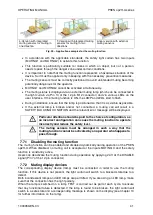
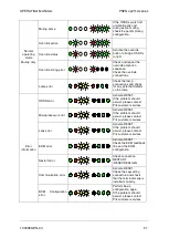
Critical error 


Switch light curtain 
on/off.  
If the problem should 
persist, please contact 
Pilz customer services. 

Supply error 


Check the power supply 
connection.  
If the problem should 
persist, please contact 
customer services. 

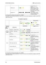
A critical error cannot be eliminated via a RESET.  
The light curtain must be switched on and off. If the error should persist, please contact Pilz 
customer services.  
 

Transmitter side (TX): 

 
A critical error cannot be eliminated via a RESET.  
The light curtain must be switched on and off. If the error should persist, please contact Pilz 
customer services.  


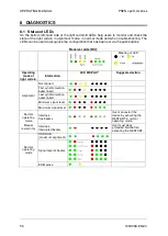
Meaning of LED 


Operating 

mode of 

light 
curtain


Information


LED DISPLAY


Suggested action


Normal 

operating 

mode


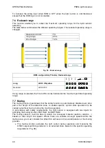
Light beams - reduced range 


Light beams - long range 


Test 


Check the wiring of the TEST.


Light beams  


Error


Microprocessor error 


Activate RESET. 


If the problem should persist, 
please contact Pilz customer 
services.


Lens error 


Activate RESET. 


If the problem should persist, 
please contact Pilz customer 
services.


BCM configuration error 


Perform basic configuration again. 


If the problem should persist, 
please contact Pilz customer 
services.


Communication error 


Activate RESET. 


Check the cascading connection 
and check that the end cap is 
installed correctly.


Critical error 


Switch light curtain on/off. 
If the problem should persist, 
please contact Pilz customer 
services.


52

1003069-EN-03

Summary of Contents for PSEN op2H-A Series

Page 1: ...PSEN op2H A series Operating Manual 1003069 EN 03 Safety light curtain...

Page 2: ...KG Copies may be made for internal purposes Suggestions and comments for improving this documentation will be gratefully received Pilz PIT PMI PNOZ Primo PSEN PSS PVIS SafetyBUS p SafetyEYE SafetyNET...

Page 3: ...ning transmitter and receiver 20 2 2 4 Using deviating mirrors 20 2 2 5 Inspections following a first time installation 21 3 MECHANICAL ASSEMBLY 23 4 ELECTRICAL CONNECTIONS 25 4 1 Connection guideline...

Page 4: ...TECHNICAL DETAILS 54 11 LIST OF AVAILABLE MODELS 55 12 DIMENSIONS 56 13 FITTINGS 57 14 ACCESSORIES 59 14 1 Rotating Mounting Bracket 59 14 2 Connection cable 60 14 3 Axial connection cable unshielded...

Page 5: ...ansmitter and receiver are synchronised optically so the two units do not have to be connected directly to each other The infrared beams that are transmitted and received are controlled and monitored...

Page 6: ...information you need regarding the functionality of the PSEN op2H A safety light curtains and the safety regulations concerning correct installation 1 1 2 Package content The following components are...

Page 7: ...beams that form the area of the protected field The resolution is closely linked to the part of the body that requires protection R 30 mm Hand protection As shown in Fig 1 the resolution depends solel...

Page 8: ...ght monitored by the PSEN op2H A corresponds to the overall height of the light curtain With reference to the previous diagram the height of the protected field can be taken from the table below Model...

Page 9: ...nce with the standard ISO 13855 this distance depends on 4 factors Response time of the light curtain the time that elapses between the beams being effectively interrupted and the OSSD contacts openin...

Page 10: ...o 2000 mm s if the calculated value S is 500 mm 1600 mm s if the calculated value S is 500 mm When using light curtains with a resolution of 40 mm the upper beam must be positioned at a height of 900...

Page 11: ...f 35 ms for t1 t2 Machine s overall stopping performance in seconds C 8 d 14 for devices with resolution 40 mm D Resolution In each case if K 2000 mm sec then S 500 mm The safety distance will then ne...

Page 12: ...f just one light axis on the safety light curtain PSEN op2H A is interrupted during the downward phase the movable workpiece carrier is stopped immediately Benefits The simple installation options and...

Page 13: ...safety distance S or that corresponds to it which guarantees that the operator cannot reach the danger zone until the hazardous machine movement of the object has come to a standstill by triggering t...

Page 14: ...tected must be greater than the device s resolution The light curtain must be installed in an environment that complies with the technical properties stated in Chapter 11 Smoke mist or dust in the wor...

Page 15: ...on the safety light curtain must be installed at a height from which access to the danger zone can be covered in full Fig 6 Fig 5 Device positioned incorrectly Fig 6 Device positioned correctly Under...

Page 16: ...ons can adversely affect how the object is detected within the protected area If the receiver RX detects a secondary beam reflected by the side reflecting surface the object may not be detected even i...

Page 17: ...2 Distances between identical light curtains Should it be necessary to install several protective devices in adjacent areas care must be taken to ensure that the transmitter on one of the pairs does...

Page 18: ...minimum safety distances required for installation with reference to some operating ranges Operating range m Minimum safety distance m 3 0 3 6 0 4 10 0 5 19 0 6 WARNING The interfering transmitter TX...

Page 19: ...op2H A series Fig 13 shows an example of an installation in which interference may occur along with two potential remedies Opaque partition Fig 13 Interference between adjacent light curtains NO YES...

Page 20: ...s should be positioned at a 45 angle to the light axes Fig 15 Using deviating mirrors When deviating mirrors are used the following precautions must be taken and conditions considered When deviating m...

Page 21: ...dirt on the mirror s reflective surface will drastically reduce the operating range 2 2 5 Inspections following a first time installation Listed below are the control measures that must be taken foll...

Page 22: ...sponse time of the light curtain and machine is within the limit values defined for calculating the safety distance see Chapter 2 2 The safety distance between the danger zones and the light curtain c...

Page 23: ...To assemble the kit with the mounting brackets place the bolts into the dedicated side guide rail Slide the insert along the groove of the metal profile Attach the bracket by tightening the M5 hexago...

Page 24: ...PSEN op2H A 30 060 1 606 2 306 2 150 PSEN op2H A 30 075 1 756 2 406 2 175 PSEN op2H A 30 090 1 906 1 506 1 200 PSEN op2H A 30 105 1 1056 1 606 1 225 PSEN op2H A 30 120 1 1206 966 150 453 PSEN op2H A 3...

Page 25: ...that the terminator cap see Chapter 13 is connected on the top of the light curtain If this connection is missing the Master and Slave units will switch to a critical communication state PSENopt Adva...

Page 26: ...ing operation with EDM enabled MUTING DEACTIVATION 24Vdc IN line N O Muting is disabled when connecting OSSD1 OSSD 2 0V OSSDs Protected field clear No voltage Protected field not clear OVERRIDE STATUS...

Page 27: ...TEST wire must be connected to the light curtain s operating voltage via a pushbutton with N O contact Use the light curtain with protection class III with SEL PELV external supplies for power supply...

Page 28: ...series connection to the OSSD outputs The safety contacts of OSSD1 and OSSD2 may not be connected in series or in parallel but must be used separately Fig 22 Should one of these configurations be used...

Page 29: ...II Fig 25 Incorrect OSSD signal load connection III NOTE The OSSDs are pulsed The following diagram shows the time characteristic of the OSSDs 115 s 500 ms 1000 ms OSSD in safe state OSSD2 OSSD1 24 V...

Page 30: ...description 1 First beam SYNC1 2 Beam of protected field 3 Last beam SYNC2 The alignment function can be activated by simultaneously switching 24 V at the input RESET RESTART ALIGN Pin 3 12 pin connec...

Page 31: ...is conducted using a test object TP 30 corresponding to the resolution see Chapter 2 2 5 E Switch off the light curtain pair and then switch it back on in normal operating mode The alignment level is...

Page 32: ...he light curtain locally without using the PSENopt Configurator CONFIRM button activates the BCM configuration mode SELECT button The different functions are run through ENABLE button Activates and de...

Page 33: ...hlights the default configuration in bold Legend for LED display in RX TX function list LED off LED is not relevant for the information in the Function column LED off LED is relevant for the informati...

Page 34: ...in zone A Led 2 OFF Led 3 OFF A B Led 2 ON red Led 3 OFF A B C Led 2 ON red Led 3 OFF A B C D Led 2 OFF Led 3 ON yellow B Led 2 ON green Led 3 ON yellow C Led 2 ON red Led 3 ON yellow List of TX funct...

Page 35: ...d the light curtain switches to a SAFE CONDITION If the object is then removed from the protected field the light curtain will resume its normal operation The response time is the time that elapses be...

Page 36: ...ger than 5 s an error is generated which blocks the light curtain Fig 32 Restart timings manual In manual restart mode the RESET RESTART ALIGN input Pin 3 of the 12 pin M12 connector RX side must be c...

Page 37: ...ated by operating the 24 V DC N O pushbutton connected to the TEST input on the TX device Pin 2 of the 5 pin M12 connector for at least 0 5 seconds The TEST disables the transmission level so the RX s...

Page 38: ...n rectified the light curtain will again switch to a blocked state 7 4 EDM The external device monitoring function EDM monitors the external devices and checks the OSSD status EDM enabled If EDM is en...

Page 39: ...0 ms time between the OSSD transition from OFF ON and the EDM test To 100 ms time between the OSSD transition from OFF ON and the EDM test two different times for the mechanical positive guided contac...

Page 40: ...ting The muting function guarantees that the safety function is automatically disabled over all or part of the height of the detection zone to enable specific cyclical work operations to be carried ou...

Page 41: ...t connected a muting call will result in a SAFETY BLOCKING CONDITION and the relevant error message will be displayed Particular attention should be paid to the choice of configuration as an incorrect...

Page 42: ...l muting T type four sensors as well as one directional muting L type two sensors T muting is used when objects can move through the light curtain in both directions L muting is used when objects move...

Page 43: ...to the sensors ending in 2 D stands for the distance at which the sensors A1 A2 or B1 B2 must be installed and depends on the package length L D L d1 stands for the maximum distance required between...

Page 44: ...The muting function ends once the time has elapsed which corresponds to a multiple of the activation delay between the two sensors this time corresponds to m T12 The value m multiplier T12 must be sel...

Page 45: ...ocity As a result d1 can be calculated in accordance with the following formula d1 cm V m s T12 s 100 Fig 44 L Muting connection BCM configuration Muting direction PWR OSSD EDM ACM LEVEL T bidirection...

Page 46: ...ns that the muting timeout may potentially never end as long as the muting conditions are present the muting function will be maintained NOTE This does not comply with the standard IEC 61496 1 and the...

Page 47: ...e The override function allows the user to disable the safety functions if the machine needs to be restarted even though one or more of the light curtain beams have detected an object in the protected...

Page 48: ...ith a T muting configuration All muting sensors are deactivated and no beams are interrupted with an L muting configuration The preset time limit has elapsed The requirements for activation are no lon...

Page 49: ...f any of the following events occurs The muting sensors are deactivated T Muting or the muting sensors are deactivated AND no beams are interrupted L Muting The timeout time elapses OVERRIDE STATE Thi...

Page 50: ...RX Meaning of LED Operating mode of light curtain Information LED DISPLAY Suggested action Alignment Not aligned First synchronisation beam linked Last synchronisation beam linked Minimum signal level...

Page 51: ...error Activate RESET If the problem should persist please contact Pilz customer services Microprocessor error Activate RESET If the problem should persist please contact Pilz customer services Lens e...

Page 52: ...r services Meaning of LED Operating mode of light curtain Information LED DISPLAY Suggested action Normal operating mode Light beams reduced range Light beams long range Test Check the wiring of the T...

Page 53: ...fied in Chapter 2 2 Access and exposure of persons between the light curtain and hazardous machine components must be prevented It is not possible to access the machine s danger zones from an unprotec...

Page 54: ...ual automatic restart EDM reset muting Protection class Class III see Ch 4 1 Current for external lamp 20 mA min 300 mA max Connections M12 12 pin M12 5 pin for receiver muting model M12 5 pin for tra...

Page 55: ...30 060 1 600 32 15 30 67 40 PSEN op2H A 30 075 1 750 40 16 30 63 38 PSEN op2H A 30 090 1 900 48 17 30 59 35 PSEN op2H A 30 105 1 1050 56 18 30 56 33 PSEN op2H A 30 120 1 1200 64 19 30 53 32 PSEN op2H...

Page 56: ...300 456 3 PSEN op2H A 30 060 1 450 606 3 PSEN op2H A 30 075 1 600 756 3 PSEN op2H A 30 090 1 750 906 3 PSEN op2H A 30 105 1 900 1056 3 PSEN op2H A 30 120 1 1050 1206 3 PSEN op2H A 30 135 1 1200 1356...

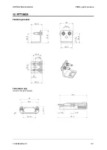
Page 57: ...OPERATING MANUAL PSEN op2H A series 13 FITTINGS Fastening bracket Terminator cap fixed to the light curtain 1003069 EN 03 57...

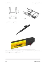
Page 58: ...G MANUAL PSEN op2H A series Tool for BCM configuration When not in use the tool for the BCM configuration can be slotted into the profile groove or into the upper section of the light curtain 58 10030...

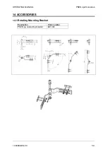
Page 59: ...OPERATING MANUAL PSEN op2H A series 14 ACCESSORIES 14 1 Rotating Mounting Bracket Description Order number PSEN op cascading bracket 631 061 1003069 EN 03 59...

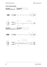
Page 60: ...PSEN op2H A series 14 2 Connection cable Description Order Number PSEN op pigtail emitter 631 055 Description Order Number PSEN op pigtail receiver m 631 057 Cable length 200 mm Cable length 200 mm 6...

Page 61: ...axial M12 5 pole 30 m 30 5 630 297 PSEN op cable axial M12 5 pole 50 m 50 5 630 364 PSEN op cable axial M12 12 pole 3 m 3 12 631 080 PSEN op cable axial M12 12 pole 5 m 5 12 631 081 PSEN op cable axi...

Reviews: