OPERATING MANUAL
PSEN op2H-A series
5 ALIGNMENT
The transmitter and receiver must be aligned to ensure the device operates correctly.
Good alignment prevents the light curtain switching incorrectly due to dust or vibration.
The optimum alignment is achieved when the optical axes of the first and last beam from the
transmitter coincide with the optical axes of the corresponding elements on the receiver.
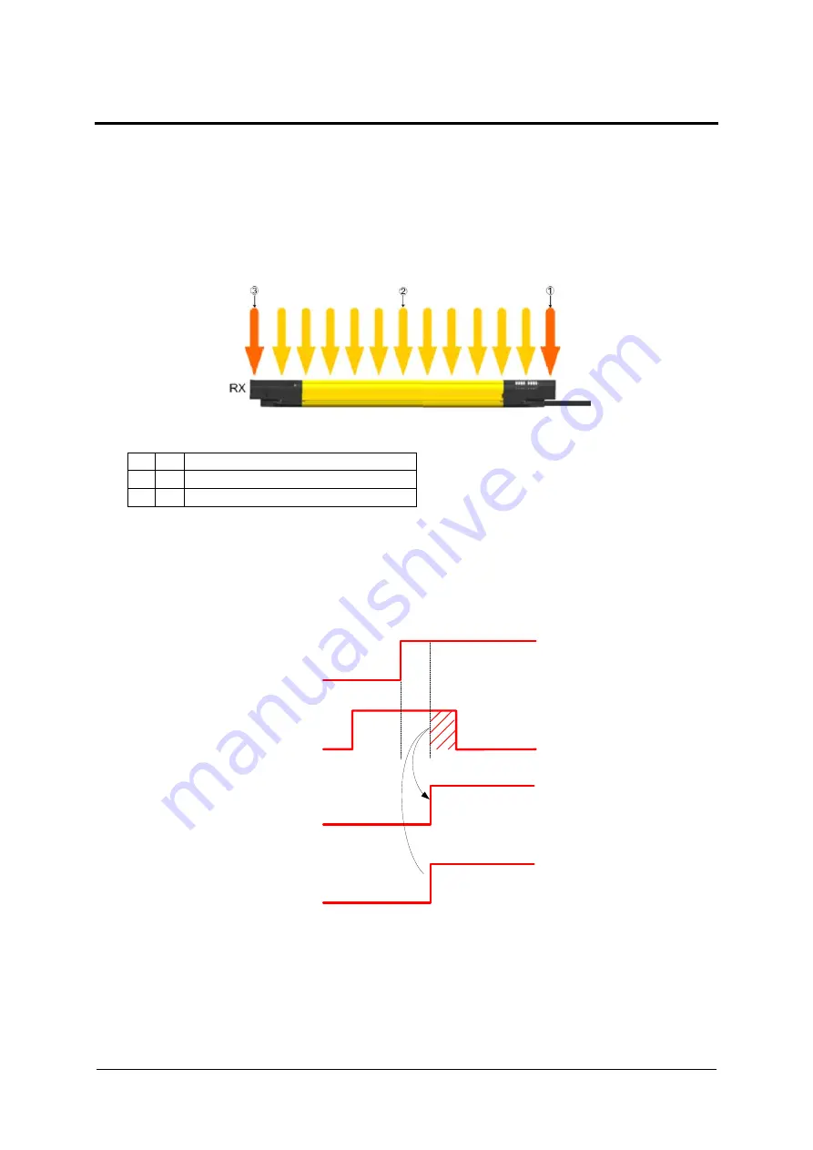
The light curtain has two synchronisation beams. The lower synchronisation beam, the first
beam in the protected field, is called SYNC1 and the synchronisation beam on the opposite
side of the light curtain, the last beam in the protected field, is called SYNC2.
The illustration shows that the first beam is on the lower edge of the light curtain, next to the
LED display. The last beam is on the opposite side, next to the terminator cap.
Fig. 27 – Beam description
1 =
First beam SYNC1
2 =
Beam of protected field
3 =
Last beam SYNC2
The alignment function can be activated by simultaneously switching 24 V at the input
RESET/RESTART/ALIGN (Pin 3/ 12-pin connector) during startup. The activated alignment
mode is shown when the second LED starts flashing (red) (see Fig. 28). Then the
RESET/RESTART/ALIGN input can be switched without voltage again. When successful
alignment has been reached, the light curtain is returned to normal operating mode by
switching off and then on again.
OFF
ON
RESET/RESTART/ALIGN
STATE OF LIGHT CURTAIN (POWER ON)
0 V DC
24 V DC
ON
OFF
RED LED FLASHES
ON
OFF
STATE OF LIGHT CURTAIN (ALIGN)
Fig. 28 – Alignment timings
In alignment mode, the light curtain is always in a safe state and the OSSD outputs are OFF.
The quality and level of the alignment is determined via the signal strength of each individual
beam in alignment mode. The two synchronization beams have a higher value level. The
user can see the alignment quality from the LED state at the lower end of the receiver.
30
1003069-EN-03


