Pilz PSEN cs2.13p ATEX Operating Manual Download Page 9

PSEN cs2.13p ATEX

Operating Manual PSEN cs2.13p ATEX
21133-EN-17

| 9

}

The connector should be protected from accidental loosening (e.g. using a cable tie).

}

The IP protection type (see 

Technical details [

 24]

) has been determined in accord-

ance with DIN EN 60529 with a safety switch that is as new.

Unit features

}

Transponder technology for presence detection

}

Pilz coding type: fully coded

}

Dual-channel operation

}

2 safety inputs for series connection of multiple safety switches

}

2 safety outputs

}

Safety Device Diagnostics (SDD)

– Safety Device Diagnostics can be used to poll sensor information, to perform actions

and to read configuration parameters

– Manipulation protection in accordance with ISO 14119 (chap. 7.2.d) is possible by

verifying the short name of the actuator through the controller via SDD communica-
tion

}

Diagnostic input for Y1 for Safety Device Diagnostics (SDD)

}

Signal output/diagnostic output Y32 for Safety Device Diagnostics

}

LED display for:

– State of the actuator
– State of the inputs
– Supply voltage/fault

}

4 directions of actuation

Function description

The safety outputs may have a high or low signal, depending on the position of the actuator
and the signal status of the inputs.
In a safe condition the safety outputs are in the OFF state.

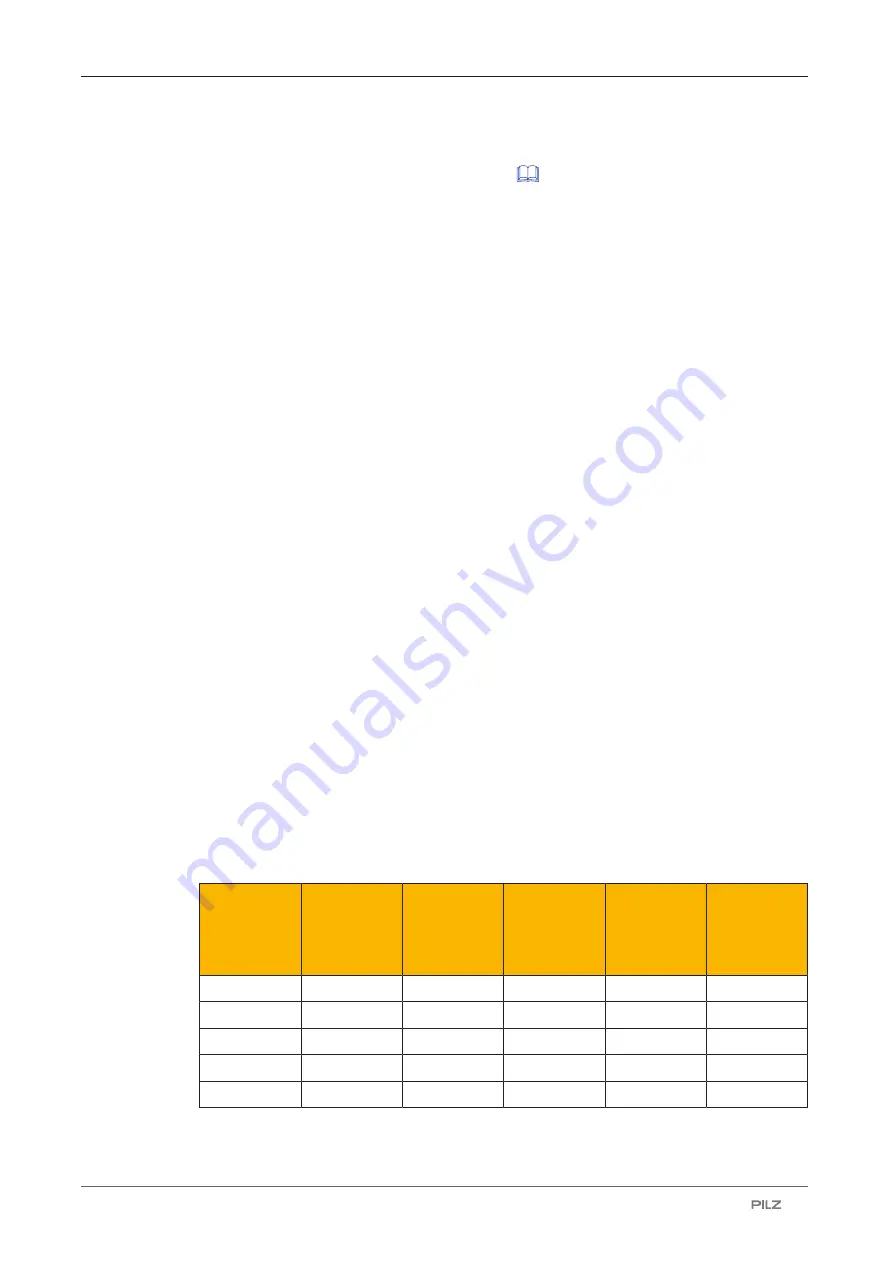
Electrical states of the inputs and outputs (when switch is ready for operation:

Power/Fault LED is green):

Actuator in

the re-

sponse

range

Safety input

S11

Safety input

S21

Safety out-

put 12

Safety out-

put 22

Signal out-

put Y32

(without use

of the SDD)

Yes

High

High

High

High

High

Yes

Low

Low

Low

Low

High

No

x

x

Low

Low

Low

Yes

High

Low

High

Low

High

Yes

Low

High

Low

High

High

x: High or low signal

Summary of Contents for PSEN cs2.13p ATEX

Page 1: ...PSEN cs2 13p ATEX Operating Manual 21133 EN 17 PSEN sensor technology...

Page 2: ...nta tion will be gratefully received Source code from third party manufacturers or open source software has been used for some components The relevant licence information is available on the Internet...

Page 3: ...nd liability 8 Disposal 8 For your safety 8 Unit features 9 Function description 9 Safety Device Diagnostics 10 Operating distances 11 Lateral and vertical offset 12 Wiring 12 Terminal assignment conn...

Page 4: ...Contents Operating Manual PSEN cs2 13p ATEX 21133 EN 17 4 EC declaration of conformity 30...

Page 5: ...portant is identified as follows DANGER This warning must be heeded It warns of a hazardous situation that poses an immediate threat of serious injury and death and indicates preventive measures that...

Page 6: ...n accordance with EN 60947 5 3 PDDB with the actuator PSEN cs2 1 EN 62061 SIL CL 3 EN ISO 13849 1 PL e Cat 4 EN ISO 14119 Coding level High type 4 The safety switch may only be used with the correspon...

Page 7: ...anual of a passive junction for example PSEN ix2 F4 code PSEN ix2 F8 code PDP67 F 4 code PSEN Y junction You will need to be conversant with the information in these documents in order to fully un der...

Page 8: ...ury and death You should prevent any possibility of the interlocking device being manipulated through the use of a spare actuator Keep the substitute actuator in a safe place and protect it from unau...

Page 9: ...fying the short name of the actuator through the controller via SDD communica tion Diagnostic input for Y1 for Safety Device Diagnostics SDD Signal output diagnostic output Y32 for Safety Device Diagn...

Page 10: ...activated and data is read If no fieldbus module of the SDD is used the diagnostic input Y1 is not used Signal output diagnostic output Y32 The status of the actuator is output If a fieldbus module of...

Page 11: ...s there are the following diagnostic options for the fieldbus module for simple wiring Information is passed on via the fieldbus module directly to the network Mappings of the signal outputs to the se...

Page 12: ...ust be followed The max cable length lmax in the input circuit is calculated from the max cable capacitance at the safety outputs see Technical data 24 the minimum permitted supply voltage at the sens...

Page 13: ...60079 14 When connecting in series consider the requirements of manipulation protection and the protection against bypassing or from overriding the safety switch EN ISO 14119 Ensure that the connecto...

Page 14: ...cs is described in the System Description Safety Device Diagnostics CAUTION Do not connect the signal output to 0 V If the signal output Y32 is connected to 0 V the safety switch may be dam aged as a...

Page 15: ...other sensors Maximum number of PSENcode sensors switched in series connections for SIL CL 3 using SDD PSENcode large design PSEN cs1 xp cs2 xp 8 When using other SDD compatible sensors the number mu...

Page 16: ...switches The may delay on de energisation is composed of max delay on de energisation actuator n 1 x max delay on de energisation of the inputs delay on de energisation of the evaluation device When m...

Page 17: ...gram series connection without SDD Actuator Actuator Control System Evaluation Device Safety switch1 Actuator Safety switch 2 Safety switch n Ex area Non Ex area FS Fail Safe S21 S11 12 A1 A2 22 0 V 2...

Page 18: ...12 22 A1 A2 A1 A2 Y1 Y1 Y1 Y32 Y32 Y32 Tx Rx Actuator Safety switch Evaluation device Fieldbus module Non Ex area Ex area Actuator Actuator Safety switch Safety switch Connection to Pilz evaluation d...

Page 19: ...to the respective evaluation device is described in the operating manual for the evaluation device Make sure that the connection is made in accordance with the specifications in the operating manual f...

Page 20: ...response range To teach in a new actuator A maximum of 8 learning procedures are possible 1 The actuator that is to be taught in must be brought into the safety switch s response range as the only tra...

Page 21: ...ipotential bonding in case of a risk of charging Make sure that the earthing is in accordance with the specifications in EN 60079 14 CAUTION Potential loss of safety function due to changed device pro...

Page 22: ...efined angle of the cable routing CAUTION Possible loss of the safety function by changing the release distance Sar with non flush installation Installing the safety switch non flush within electrical...

Page 23: ...monthly function test on the safety switch and actuator Always test the function with a connected evaluation device The safety function may only be checked by qualified personnel Refer to the notes o...

Page 24: ...Power Fault LED lights up red Error message Remedy Rectify fault and interrupt power supply Please note the different times for The switch on delay after UB is applied The recovery time of the sensor...

Page 25: ...puts No load PNOZ with relay contacts 40 nF PNOZmulti PNOZelog PSS 70 nF No load current 50 mA Inputs Number 2 Voltage at inputs 24 V DC Input current range 5 mA Max overall cable resistance Rlmax Sin...

Page 26: ...ith the standard EN 60068 2 14 Temperature range 25 40 C Max at max operating height 40 C Max at max operating height 2000 m 40 C Storage temperature In accordance with the standard EN 60068 2 1 2 Cli...

Page 27: ...r fixing screws 1 Nm Dimensions Height 75 mm Width 40 mm Depth 40 mm Actuator dimensions Height 11 mm Width 40 mm Depth 40 mm Weight of safety switch 130 g Weight of actuator 20 g Weight 150 g Where s...

Page 28: ...e this equipment NOTE This equipment has been tested and found to comply with the limits for a Class A digital device pursuant to Part 15 of the FCC Rules These limits are designed to provide reasonab...

Page 29: ...bracket cable fix Mechanical protection against defeat protecting against unau thorised cable disconnection or damage for safety switches PSENcode cs1 2 PSENcode cs5 6 M12 PSENslock 532 112 Cable Prod...

Page 30: ...e VA Decentralised passive junction V2A ring nut 773 613 Safety Device Diagnostics Product type Features Connection type Order no PSEN ix2 F4 code Interface for connecting max 4 PSEN safety sensors Sp...

Page 31: ...anual PSEN cs2 13p ATEX 21133 EN 17 31 The complete EC Declaration of Conformity is available on the Internet at www pilz com downloads Representative Norbert Fr hlich Pilz GmbH Co KG Felix Wankel Str...

Page 32: ...fetyNET p THE SPIRIT OF SAFETY are registered and protected trademarks of Pilz GmbH Co KG in some countries We would point out that product features may vary from the details stated in this document d...

Reviews: