


21
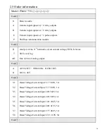
Line-neutral line
0 – 500 kV
Degree of unbalance (%)
0 – 100%
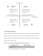
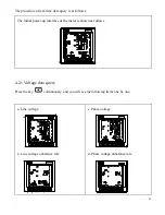
Active power/Reactive power /Apparent power
Single phase
0 - ± 100 MW/Var/VA
Total
0 - ± 100 MW/Var/VA
Power factor
Single phase
-1.000 – +1.000
Total
-1.000 – +1.000
Frequency
35 – 65 Hz
35 – 65 Hz
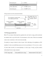
3.2 Power factor symbols
The symbols of measuring power factor conform to the stipulations of IEC, and the figure below
describes the relevant definitions.