background image

Rev. 01/2021 


19 

Power on Self Test 

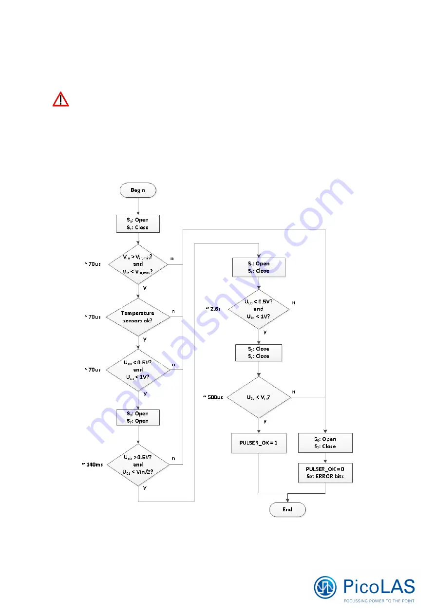
Each time the driver is powered on, it performs a test of its internal safety features. 


The MEN pin (pin 8, Master Enable) has to be HIGH, while the ENABLE pin 
(pin 7) has to be LOW for the self test to work properly.  


Changing either of the signals during the self test will result in a failure. The driver cannot be 
enabled until a self test has been performed successfully. The PULSER_OK signal will be 
pulled high when the test has been successful. (“PULSER” here stands for “diode driver) 
The test will take less than 5 seconds, but can take up to 15 seconds due to internal time outs 
if any failure is detected. The following diagram shows the individual tests and the 
approximate time it will take: 


Summary of Contents for LDP-C 120-40 NG

Page 1: ...User Manual preliminary LDP C CW 120 40 NG LDP C CW 80 40 NG PicoLAS GmbH Burgstrasse 2 52146 Würselen Phone 49 0 2405 64594 60 Fax 49 0 2405 64594 61 E Mail info picolas de Web www picolas de ...

Page 2: ...odes 17 Mechanical Dimensions 18 Power on Self Test 18 Controlling the Driver using a PLB 21 20 Menu Structure 20 Pulse Parameters 21 Trigger 21 Config 21 Defaults 22 Temperature 22 Measurement 22 If an Error Occurs 23 Controlling the Driver via PC 24 Introduction 24 Available protocols 24 Description of the RS232 Interface 24 Description of the Ethernet Interface 25 The Serial Text Interface 26 S...

Page 3: ... Setting Time 0 100 100 µs 100 µs Current Setpoint external 0 2 4 V 50 A V 0 2 0 V 50 A V LD Current sensing 50 A V 50 A V LD Voltage sensing 0 1 V V 0 1 V V Inputs LDP C BOB PLB 21 LDP C BOB PLB 21 Supply 24 48 V min 2 V above LD voltage 24 48 V min 2 V above LD voltage Max Power Dissipation 120 A 12 V out 175 W abs max 175 W abs max Dimensions in mm 100 x 180 x 74 100 x 180 x 74 Weight 1510 g 15...

Page 4: ...Rev 01 2021 3 Please pay attention to all safety warnings Change Notes Rev 01 2021 Initial release Valuable information remark Do not Please pay special attention Risk of electrical hazard ...

Page 5: ...ication and operation regime this unit may stay non cooled or must be assembled onto a heat sink No general rule value can be given It depends on the electrical power used by your diode and thus the power dissipation about 5 of this in the driver You may use a passively or an actively air water cooled device Housing All units are delivered with housing Changes are possible the units can be deliver...

Page 6: ... above your diode s compliance voltage If the red LED on the upper right of the vertical board see next side flashes 4 times it indicates that the supply voltage is too low Make sure that your power supply does not have any voltage overshoots when switching on or off Do not exceed the maximum permitted voltage of 48V 7 Set the required current If you use the plain driver apply a voltage to pin 10 ...

Page 7: ...ssis is 48 V Exceeding this voltage will damage the driver and or will cause communication errors This is not covered by warranty Strictly avoid ground loop currents through the controlling interface Front view Serial sticker Indicating product type hardware version HW and software version SW Indicating LEDs Positive supply voltage GND supply return Ethernet interface Analog interface Connect e g ...

Page 8: ...n Breakout board connector PLB Connector for PLB 21 human interface device protected against polarity reversal Vin Supply voltage must be about 4 V above laser diode compliance voltage but at least 12 V Do not exceed the limits listed in the datasheets 24 V and 48 V respectively GND Supply ground LD Positive laser diode output anode It is highly recommended to use both connectors parallel especial...

Page 9: ...ows the input and output signals of the external analog BOB connector This connector can be found on the perpendicular circuit board on the right side as shown on the previous page The BOB Breakout board is recommended for easy testing of the driver It will be replaced in the application by your machine interface The PLB 21 is a human interface device that allows for full control of all relevant d...

Page 10: ...Rev 01 2021 9 ...

Page 11: ... Pin 8 The Master Enable provides a safety interlock that disables the driver when pulled low This signal must be pulled high by the user for the driver to start up If the signal is low when the driver is powered on it will not work properly It is recommended that the user also disables the ENABLE after disabling MEN Otherwise there will be a current overshoot on the connected load When no safety ...

Page 12: ... pins with the help of a shunt resistor Inductor current additional current of all three phases laser diode current and compliance voltage are pre processed and then fed into to the external BOB connector An enable input as well as a status output is available Several security features protect the laser diode and driver from damage D10 protects the laser diode from reverse currents S9 could short ...

Page 13: ...ction S0 Security switch C1 S1 S2 S3 S4 S5 S6 S7 S8 D1 D2 D3 D4 D5 D6 D7 L1 L2 L3 L4 Buck converter C0 Input buffer capacitor S9 Shunt MosFETs short output D9 D10 Laser diode and driver protection diodes Shunt LD current monitor ...

Page 14: ... pin 4 respectively Do not shorten the output This will not do any harm to the laser driver but will result in an incorrect current measurement Keep connecting cables between power supply and driver as well as the connection between driver and laser diode as short as possible Mount the driver on an appropriate heat sink Please be aware that there might be hot surfaces be careful not to touch them ...

Page 15: ...wer to compensate for the losses in the driver itself Please take into account that the laser diode power varies strongly when the output current is modulated Although the driver is equipped with a large input capacitance of 12 mF to buffer these power peaks the power supply has to deliver the required power fast enough to avoid input voltage drops For excessive modulation of the output current th...

Page 16: ...low the shutdown temperature and the ENABLE pin is toggled During the overtemperature shutdown the PULSER_OK output pin 1 of the BOB connector is pulled low The shutdown temperature can be modified using a PLB 21 or via the USB connector Soft Start The driver implements a soft start mechanism which is activated every time the output is enabled via the ENABLE pin or the L_ON bit in the LSTAT regist...

Page 17: ...ent blink codes Nr Green LED Red LED Meaning Solution 1 on off Normal operation 2 blink 1x off Stand by 3 blink 2x off Master enable not given 4 off off Driver has no power supply Switch power on 5 off on When self test has been completed Power self test failed Contact your distributor 6 off on When driver was on before Overtemperature shutdown Set ENABLE low and wait until the driver cooled down ...

Page 18: ...le the internal current flow but wait for the soft start to be finished before enabling the output stage This will lead to a very low rise time compared to the soft start The actual rise time can be configured using the digital control Please see sections Soft Start and Timing Diagram for more details Internal The output stage is controlled by an internal pulse generator which can be enabled disab...

Page 19: ...Rev 01 2021 18 Mechanical Dimensions All dimensions in mm Over all height 69 0 mm ...

Page 20: ... of the signals during the self test will result in a failure The driver cannot be enabled until a self test has been performed successfully The PULSER_OK signal will be pulled high when the test has been successful PULSER here stands for diode driver The test will take less than 5 seconds but can take up to 15 seconds due to internal time outs if any failure is detected The following diagram show...

Page 21: ...ith yes for working the PLB 21 properly Menu Structure The following diagram shows the structure of the PLB 21 menu which affects the driver All entries are described in detail All other menu entries are described in the PLB 21 manual For detailed instructions see the PLB 21 manual Menu root Pulseparameter o Width o Reprate o Cur int ext Trigger o Mode o Edge Config o Enable o Ex Enable o Cur setp...

Page 22: ...nnector The display is updated every few seconds so it is not accurate when using analog modulation Trigger The LDP C series supports various trigger modes These are selected in this submenu Trigger Possible values are internal external and CW Please note that any change disables the output Edge This value defines the edge of the trigger signal on which the driver reacts This is not used in the cu...

Page 23: ...and modified All values are in C Dev Off This shows the user defined shutdown temperature If the LDP C CW reaches this temperature during operation the output will be disabled and an error message is displayed It can be modified within 40 80 C Temp 1 3 This shows the actual temperatures measured by the sensors of the LDP C CW Measurement This submenu holds some runtime measurement information Uin ...

Page 24: ... pulse output is switched off the pulser_ok_ext signal on the BOB connector is pulled low and a message is displayed on the PLB 21 If no other action is described on the display a toggle switch on and off of the ENABLE pin resets the error condition and re enables the driver ...

Page 25: ...n to the PLB 21 the driver also has an Ethernet interface to interface directly with a computer laptop network This interface allows communications with the driver over a network using a TCP telnet client or UDP connection See below for more details Available protocols The driver supports two protocols a text interface for direct interaction between the operator and the driver and a binary protoco...

Page 26: ...IP address but can be configured to static mode with the serial interface It can be accessed by either using a telnet client like putty or by sending UDP packets to port 23 Be aware that the telnet TCP interface does not use a full TCP stack Packet retransmissions as well as multiple connections are not supported If the driver detects a new TCP connection the current one is terminated The UDP conn...

Page 27: ...there is an error pending the response will be 10 otherwise 11 If the command requires an answer parameter this parameter is sent before the confirmation is given Example The user would like to read out the actual setpoint current User input gcurrent Enter Output of the LDP CW 12 2 CR LF 0 CR LF Example 2 The user would like to set a new setpoint current User input scurrent 25 7 Enter Output of th...

Page 28: ...nt in A Outputs the minimum output current gcurmax Current in A Outputs the maximum output current scurlimit Current in A Current in A Sets the maximum pulse current to the indicated value This value determines the maximum aviable current for the scur command A dot is used as decimal point No more then on decimal place is used 12 22 is the same as 12 2 gcurlimit Current in A Outputs the present cu...

Page 29: ... current trigger mode gtempoff Outputs the shutdown temperature gtempmax Outputs the shutdown temperature gtemphys Outputs the temperature hysterere at which the driver can be re enabled after shutdown gtempwrn Outputs the warning temperature at which the driver will show a warning gtemp Outputs the actual temperature enautoload Enables the automatic loading of default values on power on disautolo...

Page 30: ...ernal enable enable 0 or 1 Enables the driver Only used when enable_ext 1 disable 0 or 1 Disables the driver Only used when enable_ext 1 enabledhcp 0 or 1 Enables the DHCP protocol to obtain an IP address eisabledhcp 0 or 1 Disbles the DHCP protocol gip Ip address Outputs the current IP address sip Ip address Ip address Sets the IP address to the given value Only useable when enabledhcp 0 gnetmask...

Page 31: ...and 2 Bit 0 7 of the command 3 Bit 56 63 of the parameter 4 Bit 48 55 of the parameter 5 Bit 40 47 of the parameter 6 Bit 32 39 of the parameter 7 Bit 24 31 of the parameter 8 Bit 16 23 of the parameter 9 Bit 8 15 of the parameter 10 Bit 0 7 of the parameter 11 Reserved always 0x00 12 Checksum A properly received frame must be acknowledged by the recipient with an answer which is also a frame If t...

Page 32: ... 1 2 3 has the parameter 0x000000010203 GETSOFTVER Instructs the driver to send back the version number of its firmware The parameter is always 0 The answer contains the software version of the recipient The format of the answer is 0x000000 major minor revision In other words one byte for each of the three elements of the version number As example version 2 3 4 has the parameter 0x000000020304 GET...

Page 33: ...0 Temp in 0 1 C GETTEMP2 0x0102 0 0x8100 Temp in 0 1 C GETTEMP3 0x0103 0 0x8100 Temp in 0 1 C GETEMPOFF 0x0104 0 0x8100 Temp in 0 1 C GETTEMPHYS 0x0105 0 0x8100 Temp in 0 1 C LSTAT The Laser Status Register contains all internal settings for the driver The exact meaning of each bit is explained in the chapter Description of the LSTAT register Command Sent Frame Received Frame Command Parameter Com...

Page 34: ...A GETCURLIMIT 0x0505 0 0x8500 Current in 0 1A GETCURLIMITMIN 0x0506 0 0x8500 Current in 0 1A GETCURLIMITMAX 0x0507 0 0x8500 Current in 0 1A GETCUREXT 0x0508 0 0x8500 Current in 0 1A ADC The driver monitors several internal signals They can be accessed with the following commands Command Sent Frame Received Frame Command Parameter Command Parameter GETADCUDIODE 0x0600 0 0x8600 Voltage in 0 1V GETAD...

Page 35: ...AX 0x0907 0 0x8900 Reprate in Hz LAN The Lan Status Register contains all settings regarding the Ethernet interface The exact meaning of each bit is explained in the chapter Description of the LANSTAT register The IP Netmask Gateway commands expects the data the following format 192 168 1 1 0x00000101A8C0 Command Sent Frame Received Frame Command Parameter Command Parameter GETLANSTAT 0x0A00 0 0x8...

Page 36: ...pulse input 1 internal pulse generator 2 cw mode 3 TRG_EDGE Read Write Currently not used 4 ISOLL_EXT Read Write When 1 the external setpoint current is used 5 INIT_COMPLETE Read The power on test is performed successfully 6 PULSER_OK Read Indicates that the driver is in no error condition 7 ENABLE_IN Read Write When ENABLE_EXT 1 Indicates that the external enable is given When ENABLE_EXT 0 Enable...

Page 37: ...ble state Set Enable to 0 to release the lock 15 MEF_IN Read Indicates that a falling edge on the Master Enable has been detected Set Enable to 0 to clear 16 18 IOFF_CAL Read Internal use 19 23 POST_STATE Read Internal use 24 27 CAL_STATE Read Internal use 28 IS_CA Read Internal use 29 31 reserved Read Reserved ...

Page 38: ...AL Read Indicates a CRC error in the calibration The driver must be repaired 5 VCC_LOW Read Indicates that the Supply voltage is too low 6 VCC_HIGH Read Indicates that the Supply voltage is too high 7 VCC_UVLO Read Indicates that the Supply voltage has dropped during operation Check the current limitation of the power supply 8 FAILED_DEFAULT Read The default values could not be loaded during power...

Page 39: ...internal NTC 18 TEMP_SENSOR_2 Read Indicates a malfunction of an internal NTC 19 TEMP_SENSOR_3 Read Indicates a malfunction of an internal NTC 20 CB_ALWAYS_OPEN Read Used in combination with POST_FAILED 21 CB_ALWAYS_CLOSE Read Used in combination with POST_FAILED 22 HST_ALWAYS_OPEN Read Used in combination with POST_FAILED 23 HST_ALWAYS_CLOSE Read Used in combination with POST_FAILED 24 31 Reserve...

Page 40: ... Fax 49 0 2405 64594 61 E Mail info picolas de Web www picolas de CEO Dr Ing Markus Bartram Registration Court Amtsgericht Aachen Registration Number HRB 13040 Tax ID Ust IdNr DE 243221335 WEEE Reg Nr DE 28806084 No liability will be accepted for errors and omissions Technical modifications reserved ...

Reviews: