7. Working life
50
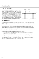
7.3.6 Load distribution
A small example: You are building a table with four lifting
columns. Each lifting column can bear 1000N. Thus, the lift-
ing columns together must bear a load Fmax = 4000N, if the
load is symmetrically in the centre of the table. If the load
moves into a corner of the table, then the lifting column has
to bear almost the entire load of 4000N under this corner.
This would lead inexorably to overload. Even at the planning
stage of your application, pay attention not only to the total
load, but also the load on the individual lifting columns.
7.4 Installation
To install the lifting columns, there are in each case four M8 tappings available in the internal and
external sections.
The recommended bolt depth is at least 20 mm and the recommended torque 15 Nm.
For guaranteed rigidity, it is essential to stipulate an adequately dimensioned foundation to ab-
sorb the stated maximum compressive and tensile forces and the torque loading. (see section 6.2)
7.5 Connecting the hand switch
You can connect the following hand switches to the lifting column:
•
6-key hand switch with display (6-pin hand switch socket) to drive lifting columns, store user-
specific positions and perform settings
•
8-key hand switch with display and base station (serial connection) to drive lifting columns,
store user-specific positions and perform settings
If you interconnect a number of lifting columns, the hand switch must be plugged into the cor-
responding socket of the first lifting column (Master lifting column).
wrong
right
Summary of Contents for Rose+Krieger RKPowerlift M Memory
Page 162: ...7 Cicli di durata 162...


