Installation
4109_en_B
PHOENIX CONTACT
11/28
3.2
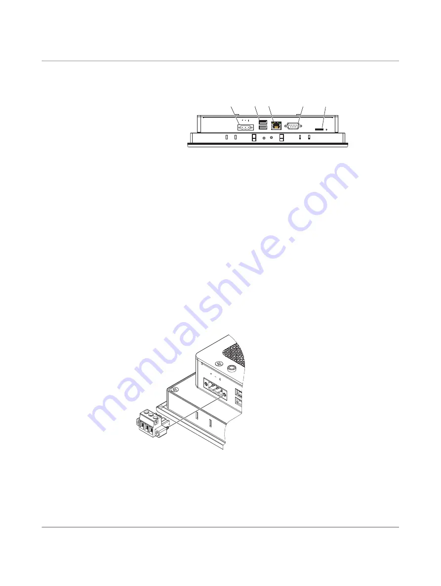
Interfaces
Figure 3
-
4
Connectors and ports
After mounting the TP 6…PS, make any necessary cable connections. The available con
-
nectors are:
– USB (USB): USB devices connect using Type A connectors. Ports are USB 2.0 ports.
– Network (LAN): An RJ45 connector allows the device to communicate on a 10/100/100
Base-T Ethernet network. The use of CAT5e or better cable is recommended.
– Serial port (RS-232/422/485): The serial port may be configured as either RS-232, RS-
422, or RS-485 port from within the configuration environment, such as Visu+ (Express)
(refer to
“Serial communication” on page 13
)
– MicroSD: The microSD slot accepts use of a microSD card to transfer data to and from
the TP 6…PS. Typical use is for transferring a common configuration between similar
devices.
3.2.1
Power connection
Figure 3
-
5
Power connection
Connect a power source to the three-position removable connector. The connector (Order
No. 1777992) accepts wire sizes from 0.5 to 2.5 mm² (24 to 12 AWG). Torque the wire-re
-
taining screws in the connector to 0.5 Nm (4.4 lb
f
-in.).
X1:PWR 24 VDC
X2:USB
X4:LAN
X6:MicroSD
PWR
X5:RS-323/422/485
X3:USB
1
2
3
4
5
1
Power connection
2
USB 2.0 ports
3
RJ45 Ethernet port
4
D-SUB 9 serial port
5
MicroSD card slot
X1:PWR 24
VDC
X2:US
B
X3:US
B
Summary of Contents for TP 6000 HMI
Page 1: ...User manual UM EN TP 6000 TP 6000 HMI for machine control...
Page 4: ...TP 6 PS 2 28 PHOENIX CONTACT 4109_en_B...
Page 8: ...TP 6 PS 6 28 PHOENIX CONTACT 4109_en_B...
Page 16: ...TP 6 PS 14 28 PHOENIX CONTACT 4109_en_B...
Page 18: ...TP 6 PS 16 28 PHOENIX CONTACT 4109_en_B...
Page 26: ...TP 6 PS 24 28 PHOENIX CONTACT 4109_en_B...


