31
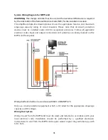
System Wiring Diagram for MPPTsolid
WARNING
:
This charge controller must be used with an external GFDI device as required
by the Article 690 of the National Electrical Code (NEC) for the installation location.
The simplified single-line drawing below shows the appropriate location and maximum
amperage capacity rating of circuit breakers. Please note that all circuit protection
devices must be installed inside UL/CSA recognized enclosures. Follow all applicable
electrical codes. Input and output connections and polarities are clearly marked on the
MPPTsolid front panel.
Wiring methods shall be in accordance with NEC, ANSI/NFPA 70.
Only use circuit protection equipment which is DC rated for the appropriate amperage
capacity and DC voltage.
Wiring Your System
Wiring to and from the MPPTsolid must be sized and installed in accordance with your
local electrical code. Installation should be performed by a qualified electrician.
Connections to and from the MPPTsolid require sealed copper ring terminal lugs with
5/16” hole.
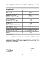
Summary of Contents for MPPTsolid
Page 2: ...2 Contents Bedienungsanleitung 3 21 User Manual 22 38 Manuel de l utilisateur 39 57 58 71...
Page 3: ...3 Ansichten Frontansicht R ckansicht...
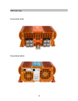
Page 22: ...22 PanelView Front panelview Back panelview...
Page 33: ...33 Opening screen Opening screen with data logging enabled Help About...
Page 39: ...39 Diff rentes vues Vue panneau avant Vue panneau arri re...
Page 58: ...58...
Page 61: ...61 MPPTsolid MPPTsolid MPPTsolid MPPT MPPTsolid PowerWizard...
Page 68: ...68 edit OK Set MPPTsolid MPPTsolid Configuration Exit...


