29
the batteries. The NEC requires that the output conductors have an amperage capacity of
1.25 X the rated current after all temperature and conduit fill corrections are calculated.
For the MPPTsolid this means conductors must be rated to carry 125 A. The minimum
cable necessary to carry the full rated output of the MPPTsolid is #2 AWG, corrections for
cable run length, conduit fill and temperature could result in a larger wire size being
necessary, to a maximum of #1/0 AWG.
The maximum input current is a function of the array Short Circuit Current (Isc), assuming
a failure of MPPTsolid that creates a short circuit on the input. In this case, multiply the Isc
rating of one panel times the number of panels in PARALLEL to determine the maximum
short circuit current.
PV input circuits require a double correction factor for over current so PV Isc (short circuit
current) must be multiplied by 1.56. All PV input wires must be sized accordingly. This
apparent over sizing is done to reflect the fact that solar modules can, and often do,
produce more than their rated power in conditions of heightened insolation and cold
temperatures. Any PV input disconnect or circuit breaker must also be rated at 1.56 of
array Isc.
Coming back to our example solar panel, the Isc for one panel is 9.18 A, and from the
charts we can see that there is almost no temperature coefficient. Assuming 5 panels in
series for 1350 W per string, and 7 strings for a maximum power of 9450 W, the maximum
short circuit current would be 9.18 x 7 or 64.26 A. Multiplying this times the safety factor
of 1.56 gives a maximum of 100 A, so likely in this case, the same wire could be used for
the input wiring as the output wiring assuming similar run lengths.
Circuit Protection
All electrical circuits require protection from over current and short circuits and the
MPPTsolid is no exception. The MPPTsolid should be installed with circuit breakers or
fused disconnects on the input and output. The MPPTsolid has a maximum current limit
of 100 A on the output and it is designed and listed to run at its maximum rating
continuously. A breaker or fuse rated at 100 amps carrying current at the highest
expected ambient temperature should be wired between MPPTsolid and the battery
bank.
The maximum input current needs to be calculated. The best way is to divide the array
power by the array maximum power voltage. In our example above, we have an array
power of 9450 W and a maximum power voltage of 160 V giving a maximum input
current of 60 A, only slightly less than the short circuit current. So the minimum circuit
breaker or fuse rating is 60 A at the highest expected ambient temperature.
If a disconnect is fitted on either the input or the output of the MPPTsolid, it should have
a minimum current rating equal to the maximum input or output current as calculated
above.
Circuit would require a 160 A input breaker. Of course the 1.56 multiplier has to be
applied specifically to your installation and if your anticipated Isc is lower than the wiring
and disconnects will reflect this.
Summary of Contents for MPPTsolid
Page 2: ...2 Contents Bedienungsanleitung 3 21 User Manual 22 38 Manuel de l utilisateur 39 57 58 71...
Page 3: ...3 Ansichten Frontansicht R ckansicht...
Page 22: ...22 PanelView Front panelview Back panelview...
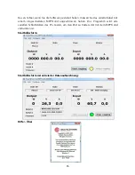
Page 33: ...33 Opening screen Opening screen with data logging enabled Help About...
Page 39: ...39 Diff rentes vues Vue panneau avant Vue panneau arri re...
Page 58: ...58...
Page 61: ...61 MPPTsolid MPPTsolid MPPTsolid MPPT MPPTsolid PowerWizard...
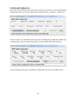
Page 68: ...68 edit OK Set MPPTsolid MPPTsolid Configuration Exit...

