


The audio decoding is done entirely via the Hercules. The IF output from the Tuner is
fed directly to either the Video-IF or the Sound-IF input, depending on the type of
concept chosen.
There are mainly two types of decoder in the Hercules, an analogue decoder that
decodes only Mono, regardless of any standards, and a digital decoder (or DEMDEC)
that can decode both Mono as well as Stereo, again regardless of any standards.
In this chassis, the analogue decoder is used in two cases:
l
It is used for AM Sound demodulation in the Europe SECAM LL' transmission.
l
It is used for all FM demodulation in AV-Stereo sets.
Diversity
The diversity for the Audio decoding can be broken up into two main concepts:
l
The Quasi Split Sound concept used in Europe and some AP sets.
l
The Inter Carrier concept, used in NAFTA and LATAM.
The UOC-III family makes no difference anymore between QSS- and Intercarrier IF,
nearly all types are software-switchable between the two SAW-filter constructions.
Simple data settings are required for the set to determine whether it is using the Inter
Carrier or the QSS concept. These settings are done via the “QSS” and “FMI” bit found
in SAM mode.
Due to the diversity involved, the data for the 2 bits are being placed in the NVM
location and it is required to write once during startup.
On top of that, it can be further broken down into various systems depending on the
region. The systems or region chosen, will in turn affect the type of sound standard that
is/are allowed to be decoded.
l
For the case of Europe, the standard consists of BG/DK/I/LL' for a Multi-System set.
There are also versions of Eastern Europe and Western Europe set and the
standard for decoding will be BG/DK and I/DK respectively. FM Radio is a feature
diversity for the Europe sets. The same version can have either FM Radio or not,
independent of the system (e.g. sets with BG/DK/I/LL' can have or not have FM
radio).
l
For the case of NAFTA and LATAM, there is only one transmission standard, which
is the M standard. The diversity then will be based on whether it has a dBx noise
reduction or a Non-dBx (no dBx noise reduction).
l
For the case of AP, the standard consists of BG/DK/I/M for a Multi-System set. The
diversity here will then depends on the region. AP China can have a Multi-System
and I/DK version. For India, it might only be BG standard.
Summary of Contents for 26FW5220
Page 1: ......
Page 5: ......
Page 39: ...SAM Menu Figure E14490 054 SAM Menu nieuw nummer ...
Page 45: ...All Models 7670 Chassis Overview ...
Page 46: ...All Models 7670 Power Supply A1 ...
Page 47: ...All Models 7670 Hercules A2 ...
Page 48: ...All Models 7670 Histogram A3 ...
Page 49: ...All Models 7670 Audio Amplifier A5 ...
Page 50: ...All Models 7670 TV Supply A6 ...
Page 51: ...All Models 7670 Scaler A7 ...
Page 52: ...All Models 7670 Scaler Interface A9 ...
Page 53: ...All Models 7670 SDRAM A10 ...
Page 54: ...All Models 7670 Flash Control A11 ...
Page 55: ...All Models 7670 HDMI A12 ...
Page 56: ...All Models 7670 PCHD MUX A13 ...
Page 57: ...All Models 7670 Supply A14 ...
Page 58: ...All Models 7670 3D Comb Filter CB ...
Page 59: ...All Models 7670 Side IO and LKB Panel D ...
Page 60: ...All Models 7670 Cinch 17 H1 ...
Page 61: ...All Models 7670 PCHD IO 17 H2 ...
Page 62: ...All Models 7670 Rear IO Cinch 23 26 H1 ...
Page 63: ...All Models 7670 PCHD IO 23 26 H2 ...
Page 64: ...All Models 7670 Front IR LED Panel J ...
Page 65: ...All Models 7670 EPLD Control PP1 ...
Page 66: ...All Models 7670 LVDS In PP2 ...
Page 67: ...All Models 7670 EPLD I O PP3 ...
Page 68: ...All Models 7670 Power Supply PP4 ...
Page 69: ...All Models 7670 Layout Tv Scaler Board Overview Top Side ...
Page 70: ...All Models 7670 Layout Tv Scaler Board Overview Bottom Side ...
Page 71: ...All Models 7670 Layout 3D Comb Filter Top Side ...
Page 72: ...All Models 7670 Layout 3D Comb Filter Bottom Side ...
Page 73: ...All Models 7670 Layout Side IO and LKB Panel Top Side ...
Page 74: ...All Models 7670 Layout Side IO and LKB Panel Bottom Side ...
Page 75: ...All Models 7670 Layout Rear IO Panel 17 Top Side ...
Page 76: ...All Models 7670 Layout Rear IO Panel 17 Bottom Side ...
Page 77: ...All Models 7670 Layout Rear IO Panel 23 26 Top Side ...
Page 78: ...All Models 7670 Layout Rear IO Panel 23 26 Bottom Side ...
Page 79: ...All Models 7670 Layout Front IR LED Panel Top Side ...
Page 80: ...All Models 7670 Layout Front IR LED Panel Bottom Side ...
Page 81: ...All Models 7670 Layout Pixel Plus Panel Top Side ...
Page 82: ...All Models 7670 Layout Pixel Plus Panel Bottom Side ...
Page 83: ...All Models 7670 Testpoint Overview TV Scaler Board Bottom Side ...
Page 84: ...All Models 7670 Testpoint Overview TV Scaler Board Top Side ...
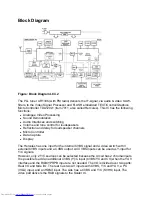
Page 85: ...All Models 7670 Wiring Diagram ...
Page 86: ...All Models 7670 Block Diagram Tuner and IF Video ...
Page 87: ...All Models 7670 Block Diagram Scaler ...
Page 88: ...All Models 7670 I2C IC Overview ...
Page 89: ...All Models 7670 Supply Voltage Overview ...
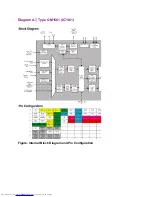
Page 109: ...Diagram A7 Type GM1501 IC7401 Figure Internal Block Diagram and Pin Configuration ...
Page 110: ...Diagram A12 Type S9993CT IC7808 Figure Internal Block Diagram ...


