


Basic Specification
The Micro Controller operates at the following supply voltages:
l
+3.3 V_dc at pins 4, 88, 94, and 109.
l
+1.8 V_dc at pins 93, 96, and 117.
l
I2C pull up supply: +3.3V_dc.
Pin Configuration and Functionality
The ports of the Micro Controller can be configured as follows:
l
A normal input port.
l
An input ADC port.
l
An output Open Drain port.
l
An output Push-Pull port.
l
An output PWM port.
l
Input/Output Port
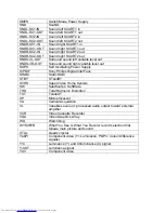
The following table shows t he ports used for the L04 control:
Table: Micro Controller ports overview
Pin
Name
Description
Configuration
97
INT0/ P0.5
IR
INT0
98
P1.0/ INT1
TV_IRQ
INT2
99
P1.1/ T0
TV_SC_COM
P1.1
102
P0.4/ I2SWS
EXT_MUTE
P0.4
103
P0.3/ I2SCLK
Lip Sync
I2SCLK
104
P0.2/ I2SDO2
NVM_WP
P0.2
105
P0.1/ I2SDO1
Lip Sync
I2SDO1
106
P0.0/ I2SDI/O
Lip Sync
I2SDI/O
107
P1.3/ T1
PC-TV_LED
P1.3
108
P1.6/ SCL
SCL
SCL
109
P1.7/ SDA
SDA
SDA
111
P2.0/ TPWM
SOUND_ENABLE
P2.0
112
P2.1/ PWM0
(for future use)
-
113
P2.2/ PWM1
(for future use)
-
114
P2.3/ PWM2
SEL_IF
P2.3
115
P3.0/ ADC0
Light Sensor – SDM ADC0
116
P3.1/ ADC1
STATUS_1
ADC1
119
P3.2/ ADC2
STATUS_2
ADC2
120
P3.3/ ADC3
KEYBOARD
ADC3
The description of each functional pin is explained below:
l
LED.
This signal is used as an indication for the Standby, Remote and Error
Indicator. Region diversity:
n
During protection mode, the LED blinks and the set is in standby mode.
n
During error conditions it blinks at a predefined rate.
n
After receiving a valid RC-5 or local keyboard command it flashes once.
n
For sets with error message indication, the LED blinks when message is active
and the set is in standby mode.
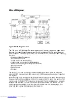
Summary of Contents for 26FW5220
Page 1: ......
Page 5: ......
Page 39: ...SAM Menu Figure E14490 054 SAM Menu nieuw nummer ...
Page 45: ...All Models 7670 Chassis Overview ...
Page 46: ...All Models 7670 Power Supply A1 ...
Page 47: ...All Models 7670 Hercules A2 ...
Page 48: ...All Models 7670 Histogram A3 ...
Page 49: ...All Models 7670 Audio Amplifier A5 ...
Page 50: ...All Models 7670 TV Supply A6 ...
Page 51: ...All Models 7670 Scaler A7 ...
Page 52: ...All Models 7670 Scaler Interface A9 ...
Page 53: ...All Models 7670 SDRAM A10 ...
Page 54: ...All Models 7670 Flash Control A11 ...
Page 55: ...All Models 7670 HDMI A12 ...
Page 56: ...All Models 7670 PCHD MUX A13 ...
Page 57: ...All Models 7670 Supply A14 ...
Page 58: ...All Models 7670 3D Comb Filter CB ...
Page 59: ...All Models 7670 Side IO and LKB Panel D ...
Page 60: ...All Models 7670 Cinch 17 H1 ...
Page 61: ...All Models 7670 PCHD IO 17 H2 ...
Page 62: ...All Models 7670 Rear IO Cinch 23 26 H1 ...
Page 63: ...All Models 7670 PCHD IO 23 26 H2 ...
Page 64: ...All Models 7670 Front IR LED Panel J ...
Page 65: ...All Models 7670 EPLD Control PP1 ...
Page 66: ...All Models 7670 LVDS In PP2 ...
Page 67: ...All Models 7670 EPLD I O PP3 ...
Page 68: ...All Models 7670 Power Supply PP4 ...
Page 69: ...All Models 7670 Layout Tv Scaler Board Overview Top Side ...
Page 70: ...All Models 7670 Layout Tv Scaler Board Overview Bottom Side ...
Page 71: ...All Models 7670 Layout 3D Comb Filter Top Side ...
Page 72: ...All Models 7670 Layout 3D Comb Filter Bottom Side ...
Page 73: ...All Models 7670 Layout Side IO and LKB Panel Top Side ...
Page 74: ...All Models 7670 Layout Side IO and LKB Panel Bottom Side ...
Page 75: ...All Models 7670 Layout Rear IO Panel 17 Top Side ...
Page 76: ...All Models 7670 Layout Rear IO Panel 17 Bottom Side ...
Page 77: ...All Models 7670 Layout Rear IO Panel 23 26 Top Side ...
Page 78: ...All Models 7670 Layout Rear IO Panel 23 26 Bottom Side ...
Page 79: ...All Models 7670 Layout Front IR LED Panel Top Side ...
Page 80: ...All Models 7670 Layout Front IR LED Panel Bottom Side ...
Page 81: ...All Models 7670 Layout Pixel Plus Panel Top Side ...
Page 82: ...All Models 7670 Layout Pixel Plus Panel Bottom Side ...
Page 83: ...All Models 7670 Testpoint Overview TV Scaler Board Bottom Side ...
Page 84: ...All Models 7670 Testpoint Overview TV Scaler Board Top Side ...
Page 85: ...All Models 7670 Wiring Diagram ...
Page 86: ...All Models 7670 Block Diagram Tuner and IF Video ...
Page 87: ...All Models 7670 Block Diagram Scaler ...
Page 88: ...All Models 7670 I2C IC Overview ...
Page 89: ...All Models 7670 Supply Voltage Overview ...
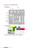
Page 109: ...Diagram A7 Type GM1501 IC7401 Figure Internal Block Diagram and Pin Configuration ...
Page 110: ...Diagram A12 Type S9993CT IC7808 Figure Internal Block Diagram ...


