


PREVENTION OF ELECTROSTATIC DISCHARGE (ESD)
Some semiconductor solid state devices can be damaged easily by static electricity. Such components
commonly are called Electrostatically Sensitive (ES) Devices, Examples of typical ES devices are
integrated circuits and some field-effect transistors and semiconductor "chip" components. The following
techniques should be used to help reduce the incidence of component damage caused by electrostatic
discharge (ESD).
1. Immediately before handling any semiconductor component or semiconductor-equipped assembly, drain
off any ESD on your body by touching a known earth ground. Alternatively, obtain and wear a
commercially available discharging ESD wrist strap, which should be removed for potential shock
reasons prior to applying power to the unit under test.
2. After removing an electrical assembly equipped with ES devices, place the assembly on a conductive
surface such as aluminum foil, to prevent electrostatic charge buildup or exposure of the assembly.
3. Use only a grounded-tip soldering iron to solder or unsolder ES devices.
4. Use only an anti-static solder removal device. Some solder removal devices not classified as "antistatic
(ESD protected)" can generate an electrical charge sufficient to damage ES devices.
5. Do not use Freon propelled chemicals. These can generate electrical charges sufficient to damage ES
devices.
6. Do not remove a replacement ES device from its protective package until immediately before you are
ready to install it (most replacement ES devices are packaged with leads electrically shorted together by
conductive foam, aluminum foil or comparable conductive material).
7. Immediately before removing the protective material from the leads of a replacement ES device, touch
the protective material to the chassis or circuit assembly into which the device will be installed.
CAUTION
: Be sure no power is applied to the chassis or circuit and observe all other safety precautions.
8. Minimize bodily motions when handling unpackaged replacement ES devices. (Otherwise harmless
motion such as the brushing together of your clothes fabric or the lifting of your feet from a carpeted
floor can generate static electricity (ESD) sufficient to damage an ES device.)
NOTE to CATV system Installer:
This reminder is provided to call the CATV system installer's attention to article 820-22 of the NEC that
provides guidelines for proper grounding and, in particular, specifies that the cable ground shall be
connected to the grounding system of the building, as close to the point of cable entry as practical.
Summary of Contents for 26FW5220
Page 1: ......
Page 5: ......
Page 39: ...SAM Menu Figure E14490 054 SAM Menu nieuw nummer ...
Page 45: ...All Models 7670 Chassis Overview ...
Page 46: ...All Models 7670 Power Supply A1 ...
Page 47: ...All Models 7670 Hercules A2 ...
Page 48: ...All Models 7670 Histogram A3 ...
Page 49: ...All Models 7670 Audio Amplifier A5 ...
Page 50: ...All Models 7670 TV Supply A6 ...
Page 51: ...All Models 7670 Scaler A7 ...
Page 52: ...All Models 7670 Scaler Interface A9 ...
Page 53: ...All Models 7670 SDRAM A10 ...
Page 54: ...All Models 7670 Flash Control A11 ...
Page 55: ...All Models 7670 HDMI A12 ...
Page 56: ...All Models 7670 PCHD MUX A13 ...
Page 57: ...All Models 7670 Supply A14 ...
Page 58: ...All Models 7670 3D Comb Filter CB ...
Page 59: ...All Models 7670 Side IO and LKB Panel D ...
Page 60: ...All Models 7670 Cinch 17 H1 ...
Page 61: ...All Models 7670 PCHD IO 17 H2 ...
Page 62: ...All Models 7670 Rear IO Cinch 23 26 H1 ...
Page 63: ...All Models 7670 PCHD IO 23 26 H2 ...
Page 64: ...All Models 7670 Front IR LED Panel J ...
Page 65: ...All Models 7670 EPLD Control PP1 ...
Page 66: ...All Models 7670 LVDS In PP2 ...
Page 67: ...All Models 7670 EPLD I O PP3 ...
Page 68: ...All Models 7670 Power Supply PP4 ...
Page 69: ...All Models 7670 Layout Tv Scaler Board Overview Top Side ...
Page 70: ...All Models 7670 Layout Tv Scaler Board Overview Bottom Side ...
Page 71: ...All Models 7670 Layout 3D Comb Filter Top Side ...
Page 72: ...All Models 7670 Layout 3D Comb Filter Bottom Side ...
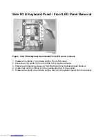
Page 73: ...All Models 7670 Layout Side IO and LKB Panel Top Side ...
Page 74: ...All Models 7670 Layout Side IO and LKB Panel Bottom Side ...
Page 75: ...All Models 7670 Layout Rear IO Panel 17 Top Side ...
Page 76: ...All Models 7670 Layout Rear IO Panel 17 Bottom Side ...
Page 77: ...All Models 7670 Layout Rear IO Panel 23 26 Top Side ...
Page 78: ...All Models 7670 Layout Rear IO Panel 23 26 Bottom Side ...
Page 79: ...All Models 7670 Layout Front IR LED Panel Top Side ...
Page 80: ...All Models 7670 Layout Front IR LED Panel Bottom Side ...
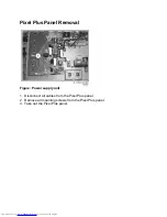
Page 81: ...All Models 7670 Layout Pixel Plus Panel Top Side ...
Page 82: ...All Models 7670 Layout Pixel Plus Panel Bottom Side ...
Page 83: ...All Models 7670 Testpoint Overview TV Scaler Board Bottom Side ...
Page 84: ...All Models 7670 Testpoint Overview TV Scaler Board Top Side ...
Page 85: ...All Models 7670 Wiring Diagram ...
Page 86: ...All Models 7670 Block Diagram Tuner and IF Video ...
Page 87: ...All Models 7670 Block Diagram Scaler ...
Page 88: ...All Models 7670 I2C IC Overview ...
Page 89: ...All Models 7670 Supply Voltage Overview ...
Page 109: ...Diagram A7 Type GM1501 IC7401 Figure Internal Block Diagram and Pin Configuration ...
Page 110: ...Diagram A12 Type S9993CT IC7808 Figure Internal Block Diagram ...


