


Tuner and IF
A Philips UR13xx Tuner with second input (for FM Radio) is used in the TV board. The
SIF and FM signals are decoded by the Hercules. Tuning is done via I2C.
Video IF Amplifier
The IF-filter is integrated in a SAW (Surface Acoustic Wave) filter. One for filtering IF-
video (1328) and one for IF-audio (1330). The type of these filters is depending of the
standard(s) that has to be received.
The output of the tuner is controlled via an IF-amplifier with AGC-control. This is a
voltage feedback from pin 31 of the Hercules to pin 1 of the tuner. The AGC-detector
operates on top sync and top white level. AGC take-over point is adjusted via the
service alignment mode 'Tuner' - 'AGC'. If there is too much noise in the picture, then it
could be that the AGC setting is wrong. The AGC-setting could also be mis-aligned if
the picture deforms with perfect signal; the IF-amplifier amplifies too much.
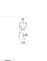
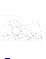
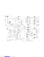
Video: TV Part (diagrams A1, A2, and A3)
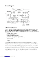
Figure: Block diagram video processing
Summary of Contents for 26FW5220
Page 1: ......
Page 5: ......
Page 39: ...SAM Menu Figure E14490 054 SAM Menu nieuw nummer ...
Page 45: ...All Models 7670 Chassis Overview ...
Page 46: ...All Models 7670 Power Supply A1 ...
Page 47: ...All Models 7670 Hercules A2 ...
Page 48: ...All Models 7670 Histogram A3 ...
Page 49: ...All Models 7670 Audio Amplifier A5 ...
Page 50: ...All Models 7670 TV Supply A6 ...
Page 51: ...All Models 7670 Scaler A7 ...
Page 52: ...All Models 7670 Scaler Interface A9 ...
Page 53: ...All Models 7670 SDRAM A10 ...
Page 54: ...All Models 7670 Flash Control A11 ...
Page 55: ...All Models 7670 HDMI A12 ...
Page 56: ...All Models 7670 PCHD MUX A13 ...
Page 57: ...All Models 7670 Supply A14 ...
Page 58: ...All Models 7670 3D Comb Filter CB ...
Page 59: ...All Models 7670 Side IO and LKB Panel D ...
Page 60: ...All Models 7670 Cinch 17 H1 ...
Page 61: ...All Models 7670 PCHD IO 17 H2 ...
Page 62: ...All Models 7670 Rear IO Cinch 23 26 H1 ...
Page 63: ...All Models 7670 PCHD IO 23 26 H2 ...
Page 64: ...All Models 7670 Front IR LED Panel J ...
Page 65: ...All Models 7670 EPLD Control PP1 ...
Page 66: ...All Models 7670 LVDS In PP2 ...
Page 67: ...All Models 7670 EPLD I O PP3 ...
Page 68: ...All Models 7670 Power Supply PP4 ...
Page 69: ...All Models 7670 Layout Tv Scaler Board Overview Top Side ...
Page 70: ...All Models 7670 Layout Tv Scaler Board Overview Bottom Side ...
Page 71: ...All Models 7670 Layout 3D Comb Filter Top Side ...
Page 72: ...All Models 7670 Layout 3D Comb Filter Bottom Side ...
Page 73: ...All Models 7670 Layout Side IO and LKB Panel Top Side ...
Page 74: ...All Models 7670 Layout Side IO and LKB Panel Bottom Side ...
Page 75: ...All Models 7670 Layout Rear IO Panel 17 Top Side ...
Page 76: ...All Models 7670 Layout Rear IO Panel 17 Bottom Side ...
Page 77: ...All Models 7670 Layout Rear IO Panel 23 26 Top Side ...
Page 78: ...All Models 7670 Layout Rear IO Panel 23 26 Bottom Side ...
Page 79: ...All Models 7670 Layout Front IR LED Panel Top Side ...
Page 80: ...All Models 7670 Layout Front IR LED Panel Bottom Side ...
Page 81: ...All Models 7670 Layout Pixel Plus Panel Top Side ...
Page 82: ...All Models 7670 Layout Pixel Plus Panel Bottom Side ...
Page 83: ...All Models 7670 Testpoint Overview TV Scaler Board Bottom Side ...
Page 84: ...All Models 7670 Testpoint Overview TV Scaler Board Top Side ...
Page 85: ...All Models 7670 Wiring Diagram ...
Page 86: ...All Models 7670 Block Diagram Tuner and IF Video ...
Page 87: ...All Models 7670 Block Diagram Scaler ...
Page 88: ...All Models 7670 I2C IC Overview ...
Page 89: ...All Models 7670 Supply Voltage Overview ...
Page 109: ...Diagram A7 Type GM1501 IC7401 Figure Internal Block Diagram and Pin Configuration ...
Page 110: ...Diagram A12 Type S9993CT IC7808 Figure Internal Block Diagram ...


