background image

20

T

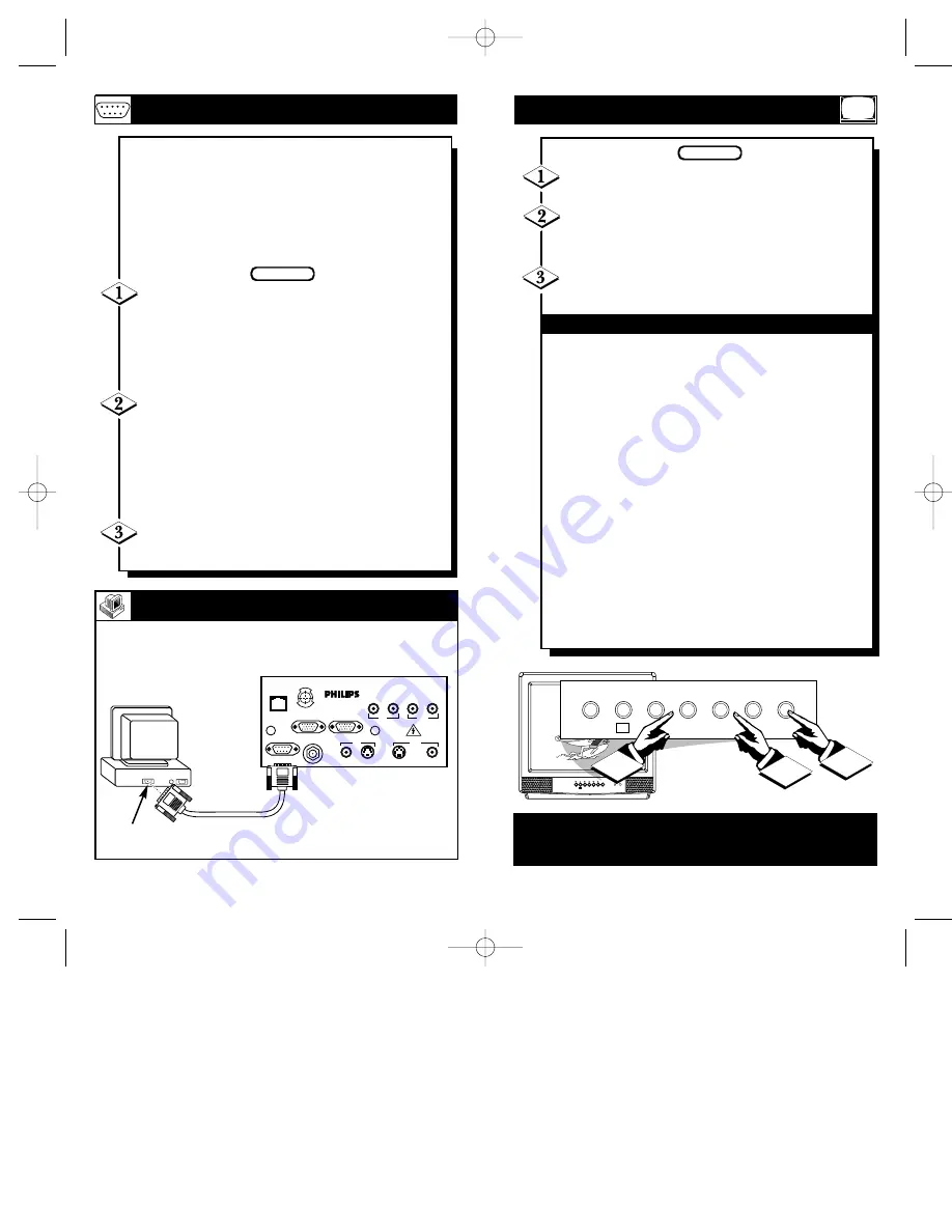
he ScanCard II assembly is equipped

with a RS 232 (Serial) Input. When a

computer’s Serial Port is hooked to the Scan
Card II through the RS 232 input, the com-
puter can control the various functions of the
television. (Refer to SmarkLink specifications
available under DNA.)

It is always a good idea to remove the TV’s,

and the computer’s, AC power cords from the

wall socket before beginning the connections.
The RS 232 (Serial) Input accepts signals from
VGA and MAC compatible computers that have
external Serial Ports.

For PC/MACs with Serial Ports: Plug a

Serial cable into the RS 232 (Serial) Input termi-

nal on the back of a commercial TV equipped
with the ScanCard II. Then attach the other end of
the Serial cable to the Serial Output Port on the
back of the computer. (Secure the plugs by tight-
ening the thumb screws.)

Reattach the AC Power cords to the wall sock-

ets before powering on the units.

BEGIN

RS 232 I

NPUT

CLONE

PORT

S-VIDEO

VIDEO

AUDIO

RF IN

VIDEO

AUDIO

IN

OUT

OUT

IN

S-VIDEO

VGA/S-AUDIO

S-AUDIO

RS 232

VGA IN

VGA OUT

E

N H

A NCE

D

FOCUS

ScanCard  II

BACK OF THE TV

WITH SCANCARD II

Serial Cable

Desk Top/Lap Top

PC/Macintosh Computer

with a Serial Port

(also Power Macintosh)

Serial Output

RS 232 IN(put)

RS 232 C

ONNECTIONS

21

BEGIN

T

ELEVISION

O

PERATION

Press the POWER button to turn the TV ON. 

Press the VOLUME UP (

) or DOWN (

)

button to adjust the sound level.

Press the CHANNEL UP (

) or DOWN (

)

button to select TV channels.

The TELEVISION CONTROL PANEL

MENU

Button - Brings the on-screen menu up and allows

the user to scroll thru the options.

SLEEP Button - With the ScanCard II assembly installed, the
Sleep option at the television control panel is rendered inopera-
ble.

MENU

Button - Will clear the screen when the on-screen

menu is visible.

CC Button - Will bring up the Closed Captioning options.
Repeated pressing of this button will allow the user to change
those options. (Will not operate when tuned to the VGA channel.)

CHANNEL

▼▲

Buttons - Use these buttons to scroll thru

available channels. These buttons will also allow you to scroll
thru the on-screen menu options when displayed.

VOLUME

▼▲

(- or +) Buttons - Use these buttons to

increase or decrease the audio level output of the TV. The (-) or
(+) function for these buttons is to select certain options from
within the on-screen menu.

POWER Button - Toggle between turning the TV ON and OFF.

6

+

MENU

CH

VOL

POWER

SLEEP

CC

1

3

2

Note: The KEYBOARD Buttons can be controlled using the

“FRONT KEYPAD” feature within the “Commercial Settings”

menu (refer to page 30 for more details).

SCAN 2  10/3/00  10:49 AM  Page 20

Summary of Contents for 21-STEREO INSTITUTIONAL CTV SCN720C

Page 1: ...OWNER S MANUAL AND SET UP GUIDE E NHANCE D FOCUS T E L E V I S I O N IndustryStandards ScanCard II Professional Color Television SCAN 2 10 3 00 10 49 AM Page 1 ...

Page 2: ...e correspon dante de la prise et pousser jussssqu au fond t s CAUTIO N RISK OF ELECTRIC SHOCK DO NOT OPEN CAUTION TO REDUCE THE RISK OF ELECTRIC SHOCK DO NOT REMOVE COVER OR BACK NO USER SERVICEABLE PARTS INSIDE REFER SERVICING TO QUALIFIED SERVICE PERSONNEL KNOW THESE SAFETY SYMBOLS 3 2 TABLE OF CONTENTS Getting Started Warning Precautions 2 Introduction 4 Features 5 Unpacking and Assembly 6 7 In...

Page 3: ...ser Disc Players CD i Players Web Browsers and Satellite Systems With use of a T374AH Setup Remote see T374AH Remote Control Instructions part IB7166E002 for complete details the installer can adjust the normal commercial tele vision functions with the exception of the BRIGHTNESS and PICTURE settings for VGA and NON VGA display modes ScanCard II will store a separate set of BRIGHT NESS and PICTURE...

Page 4: ...nCard II Assembly Cover the ScanCard II Circuit Board the ScanCard II Jack Panel Board the RF Input Plug Retaining Nut Hex Head Screw and the Remote Control Unit Unfold the Cardboard holders to release the two Circuit Boards and use the following instructions to assemble the unit Line up the 25 pin connector on the ScanCard II Circuit board with the 25 pin con nector on the Jack Panel board Carefu...

Page 5: ...mote Control see T374AH Remote Control Instructions part IB7166E002 for complete details Note This is not the remote supplied with the ScanCard II package Start by unplugging the AC power cord from the wall socket Remove the hex head screws holding the card cover in place Slide the card cover off Be careful when pulling the Antenna jack RF IN out of its plug Insert the ScanCard II with its compone...

Page 6: ...na Twin Lead 300 Ohm Outdoor VHF Antenna Round 75Ω Cable Twin Lead Wire Round End OPTIONAL HOOKUPS 10 Acombination antenna receives normal broadcast channels VHF 2 13 and UHF 14 69 Your connection is easy since there is only one 75Ω ohm antenna plug on the back of your TV and that s where the antenna goes If you have more than one antenna please refer to the diagram at the bottom of page 11 for ad...

Page 7: ...el Back of TV Round Cable 75Ω Ohm Cable TV Converter Box Connection Cable TV Company ScanCard II Jack Panel 12 Your Cable TV input into your home may be a single 75 ohm cable or a Converter Box installation In either case the connection to the TV is very easy Just put the threaded end of the cable signal to the TV s antenna plug and screw it down tight If your Cable TV signal is a single round cab...

Page 8: ...ScanCard II Assembly Optional Hook Up of Second TV Using Loop Thru Outputs Audio RCA Phono Plug Cable not sup plied Jack Panel of Optional Mono VCR Back of TV Front Control Panel of TV AUDIO VIDEO INPUTS You can view the playback of VCR tapes Video Disc Players Camcorders etc by using the AUDIO and VIDEO INPUT jacks on the ScanCard II Cover assembly For example Use the following steps to view the ...

Page 9: ... VCR Optional VGA S AUDIO S VIDEO Hook Up of Second TV Using Loop Thru Outputs S VIDEO INPUTS The S uper Video connection on the rear of the TV can give you better picture detail and clarity for the playback of S VHS VCR tapes rather than the normal antenna picture connections Note The VCR or accessory device must have a S VIDEO OUT put jack in order for you to complete the steps and connections s...

Page 10: ...wing are suggested computer connec tions to the ScanCard II It is always a good idea to remove the TV s and the computer s AC power cords from the wall socket before beginning the connections The VGA Input accepts signals from VGA and MAC compatible computers without the need for any additional hardware For PC Applications Plug the VGA cable into the VGA Input terminal on the back of a commer cial...

Page 11: ...lso Power Macintosh Serial Output RS 232 IN put RS 232 CONNECTIONS 21 BEGIN TELEVISION OPERATION Press the POWER button to turn the TV ON Press the VOLUME UP or DOWN button to adjust the sound level Press the CHANNEL UP or DOWN button to select TV channels The TELEVISION CONTROL PANEL MENU Button Brings the on screen menu up and allows the user to scroll thru the options SLEEP Button With the Scan...

Page 12: ...ature ONLY works when tuned to the VGA channel STATUS EXIT Press this button to clear the screen of the menu and save function changes made within the on screen menus SELECT M Press this button to bring up the on screen menu options Also may be used to select items within the menu CH annel Press this button to scroll through all available channels A CH Press this button to toggle between the prese...

Page 13: ...ORE PRESETS This menu can be accessed by the MENU or ADJUST buttons on the remote TV PICTURE SETUP BRIGHTNESS PICTURE RESTORE PRESETS EXIT MENU PRESS OR TO EXIT EXIT the menu using the or buttons ScanCard II has two different operation modes Consumer and Commercial When in the Consumer mode all available menu items and tuning options are fully enabled with the exception of the COMMER CIAL SETTING ...

Page 14: ...CTURE SETUP BRIGHTNESS PICTURE VGA AUDIO ON INPUT TYPE PC ADJUST VGA IMAGE RESTORE PRESETS EXIT MENU PRESS TO ADJUST IMAGE Press the button to access the VGA IMAGE ADJUSTMENT menu When you access the ADJUST VGA IMAGE menu the following items can be changed or adjusted HORIZONTAL SIZE and POSITION VERTICAL SIZE and POSITION VGA GAIN LEVEL COLOR INTENSITY and a FLICK ER FILTER For more details refer...

Page 15: ...ER FILTER ON EXIT MENU FOR LOW FOR HIGH Press the button to set the COLOR INTENSI TY to LOW or the button to set it to HIGH VGA IMAGE ADJUSTMENT HORIZONTAL SIZE VERTICAL SIZE HORIZONTAL POSITION VERTICAL POSITION VGA GAIN LEVEL HIGH COLOR INTENSITY HIGH FLICKER FILTER ON EXIT MENU FOR OFF FOR ON To activate the FLICKER FILTER press the button To turn it OFF press the button VGA IMAGE ADJUSTMENT HO...

Page 16: ...S MENU Mode Press the or button to change the TV s oper ation mode There are two different operating modes avail able CONSUMER or COMMERCIAL When the ScanCard II is in the CONSUMER mode all menu items and tuning options are fully operational In this mode the user will be able to access the ScanCard II s internal TV PICTURE SETUP VGA PICTURE SETUP and the TV s SETUP menus with the ScanCard II remot...

Page 17: ... seconds after the channel change and then disappear With ScanCard II installed REMINDER should be in the OFF position On Channel This function will determine what channel the TV will tune to at initial turn ON Tune any channel and press the button The TV will tune to that channel every time it is turned ON Press the button and the TV will at turn on tune to the last channel tuned before turn OFF ...

Page 18: ...t may not be turned OFF except by removing power Press the button for normal POWER ON OFF control Displays The NO DISPLAYS function disables any on screen displays except the Sleep Timer and the Mute Press the button to activate this function and the button for standard displays With the ScanCard II installed set Displays to STANDARD Keyboard The OFF selection lockouts or disables all functions fr...

Page 19: ...URE BRIGHTNESS PICTURE VGA AUDIO INPUT TYPE The Zoom feature will enlarge the on screen display twice its normal size only when tuned to the VGA channel Defaulting to the upper left corner the picture can be panned by using the cursor keys on the remote control When tuned to the VGA channel press the ZOOM button on the remote control The on screen display will appear twice as large Defaulting to t...

Page 20: ...nePort Interface Menu An on screen listing of feature controls shown on the Television screen that are made available for user adjustments Multichannel Television Sound MTS The broad cast standard that allows for stereo and Second Audio Programs SAP to be transmitted with the TV picture RS 232 Connector Electrical Interface on the Scan Converter jack panel that allows a computer to commu nicate wi...

Page 21: ...1997 Philips Consumer Electronics Company IB7957E001 E NHANCE D FOCUS T E L E V I S I O N SCAN 2 10 3 00 10 49 AM Page 40 ...

Reviews: