Philips Saeco Exprelia Series Service Manual Download Page 39

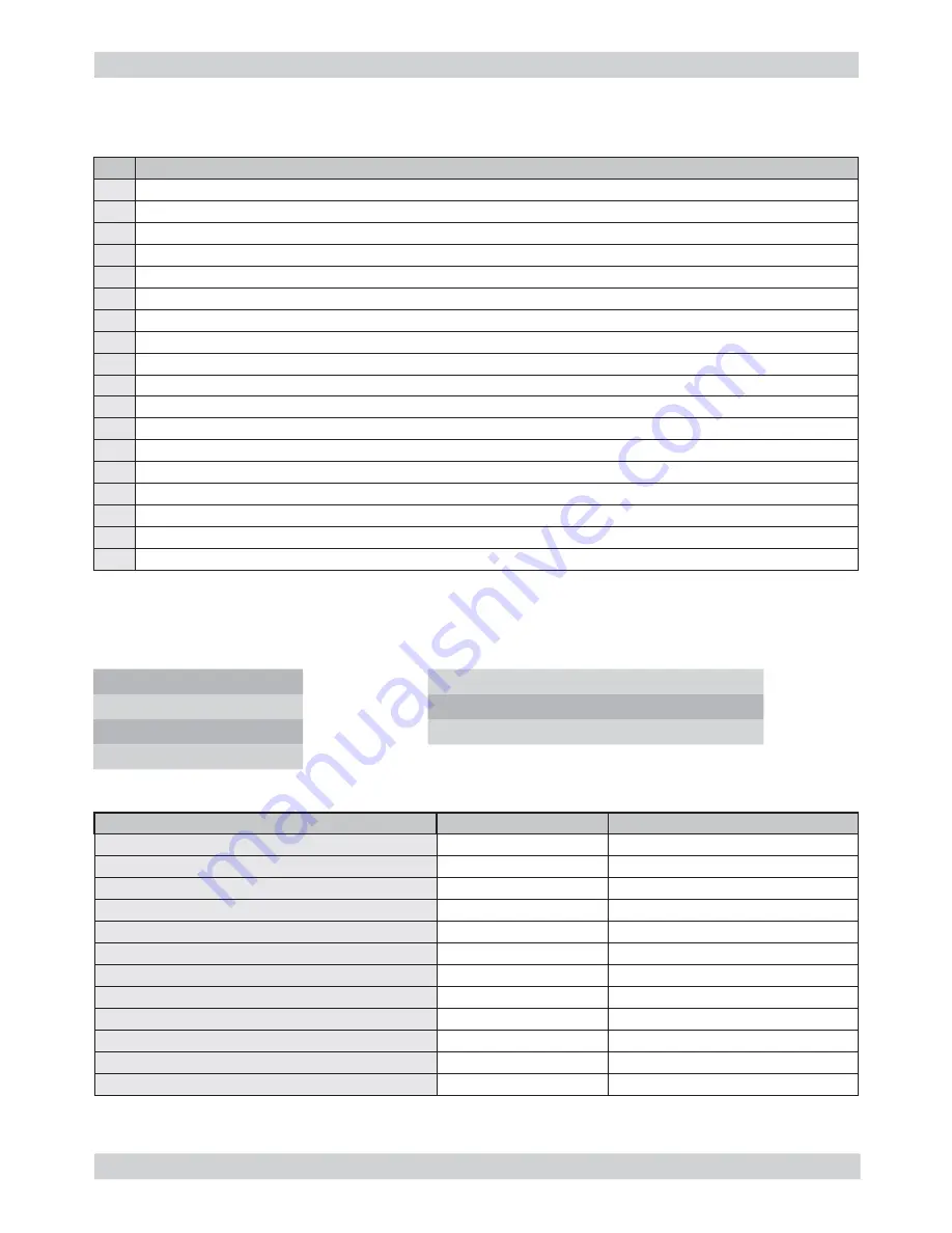
EXPRELIA                                                                                        06 STANDARD CHECKS

Saeco International Group

Rev. 00 / June 2010

Page       / 02


Action

1

Visual inspection (transport damage)

2

Machine data check (rating plate)

3

Operational check / problem analysis

4

Opening machine

5

Visual inspection

6

Operational tests

7

Repairing the faults encountered

8

Checking any modi

fi

 cations (view info, new sw, etc.)

9

Service activities in accordance with the operating schedule

10

Internal cleaning

11

Operational test while the appliance is open

12

Assembly

13

Final inspection test

14

Draining the circuit (in winter)

15

External cleaning

16

Lubricating the brewing unit with suitable grease

17

Insulation test HG 701 (dielectric)

18

Documentation 

S

Replacement

P

Cleaning

ES

Visual inspection

TR

Noise test

D

Descaling

R

Adjustment

CF

Operative check

Component

Action

Support/tool

Water 

fi

 lter:

P/S/CF

Water tank lip seal

S/CF

Boiler pin O-ring

S/CF

Brewing unit

ES/P/CF

Grease solvent / Grease

Hoses, attachments and Oetiker clamps

ES/CF

Coffee circuit pump

ES/TR/CF

Hot water/steam circuit pump

ES/TR/CF

Gearmotor:

ES/TR/CF

Coffee grinder

P/R/CF

Vacuum cleaner / brush

Water circuit

D/CF

Saeco descaler

Frothing valve assembly

ES/S/CF

Multi-way valve (solenoid pilot)

ES/S/CF

 6.2. 

Service 

schedule

 6.1. 

Repair 

schedule

01

Summary of Contents for Exprelia Series

Page 1: ...3 3 3 Operation cleaning and maintenance 5 4 Operating logic 4 1 Water circuit 1 4 2 Frother unit valve assembly 2 4 2 1 General carafe assembly 2 4 3 Multi way valve 4 4 4 Coffee cycle 5 4 5 Single m...

Page 2: ...Gearmotor 5 7 12 Multi way valve 6 7 13 Frother unit valve assembly 6 7 14 Door tube coupling 6 7 15 Dispenser assembly 7 7 16 Steam pipe assembly 7 7 17 General carafe card assembly 8 7 18 Teflon pi...

Page 3: ...Saeco International Group Rev 00 June 2010 EXPRELIA CHAPTER 1 INTRODUCTION...

Page 4: ...enter Programmer for programming and diagnostics mode 1 3 Material Description Notes Thermal paste Heating element 200 C Descaler Saeco descaler Grease solvent Personal choice Silicone grease Safe to...

Page 5: ...y interface X X With satin finished steel parts X With ABS parts X Milk carafe X X Clean automatic milk circuit washing X X Automatic dosing SAS X X Dispensed coffee memory capacity X X Dispensed milk...

Page 6: ...ull tray floating indicator Drip tray grille Control panel Water tank Coffee bean hopper with lid Compartment for pre ground coffee Service hatch SBS Milk carafe attachment Milk carafe Hot water steam...

Page 7: ...ge 04 1 6 2 Internal machine parts 04 Turbine Multi way valve Coffee boiler Water level capacitive sensor Power card Steam boiler Water pump Steam pump Frother unit valve assembly Coffee grinder Groun...

Page 8: ...Saeco International Group Rev 00 June 2010 EXPRELIA CHAPTER 2 TECHNICAL SPECIFICATIONS...

Page 9: ...x 13 15 bar with reciprocating piston and thermal switch 120 C 48 W 230V 50 Hz 120V 60Hz 100V 50 60 Hz Steam pump Ulka MF with reciprocating piston 230V 50 Hz 120V 60Hz 100V 50 60 Hz Overpressure valv...

Page 10: ...y manually or automatically after 60 if at least one coffee has been dispensed before switching off No of pulses 130 100 Stopping option Yes by pressing any key Yes by pressing any key User disable op...

Page 11: ...eg drawer after double coffee as last product dispensed 15 lots of dregs 16 lots of dregs Reset dreg counter The dreg drawer must be emptied only when prompted by the machine ensuring the machine is s...

Page 12: ...Saeco International Group Rev 00 June 2010 EXPRELIA CHAPTER 3 CHAPTER 3 USER INSTRUCTIONS USER INSTRUCTIONS...

Page 13: ...the MENU button to go to the machine s main menu Press the OK button to go to the BEVERAGE MENU Quantity of Coffee this section enables programming the quantity of coffee to be ground for making the b...

Page 14: ...ss power but takes longer to dispense milk beverages because the steam boiler is needed To disable buzzers This function governs activation of the boilers in the appliance for energy saving GENERAL ME...

Page 15: ...function is used to run the washing cycle for the brewing unit MAINTENANCE METERS FOR CARAFE CLEANING DESCALING UNIT CLEANING CLEAN CARAFE OFF ON MAINTENANCE FACTORY SETTINGS This function allows the...

Page 16: ...filter with a new one The alarm is displayed only if the enable filter function is ON An even has occurred that requires restarting the appliance Take note of the code E xx shown at the bottom Red LED...

Page 17: ...Without water filter With water filter 1 Soft up to 7 dH 240 litres 480 000 pulses 480 litres 960 000 pulses 2 Medium 7 14 dH 120 litres 240 000 pulses 240 litres 480 000 pulses 3 Hard 15 21 dH 60 lit...

Page 18: ...Saeco International Group Rev 00 June 2010 EXPRELIA CHAPTER 4 OPERATING LOGIC...

Page 19: ...EXPRELIA 04 OPERATING LOGIC Saeco International Group Rev 00 June 2010 Page 11 4 1 Water circuit COLD WATER HOT WATER STEAM STEAM HOT WATER 01...

Page 20: ...for carafe present missing indication and dispenser positioning 4 2 Frother unit valve assembly Features and requirements Maximum operating pressure 3 bar Maximum pressure in the water steam circuit...

Page 21: ...lean steam Air Milk based beverages steam hot water steam CARAFE ATTACHMENT DC1 pressure relief valve assembly DC2 steam valve DC3 air valve DC4 clean valve steam DC5 hot water steam valve Functional...

Page 22: ...bar Filling the circuit the solenoid valve opens drain position and the pump is activated automatically refilling the circuit by expelling the air in the pipe Unit discharge before the unit descends i...

Page 23: ...constant level Coffee cycle The coffee grinder starts the grinding process controlled by pulses generated by a sensor 1 The gearmotor brewing unit moves to the dispensing position 2 Preliminary dispe...

Page 24: ...res see table 4 6 Temperature sensor adjustment Temp C R nom k R 20 61 465 8 6 50 17 599 5 9 75 7 214 4 1 80 6 121 3 7 85 5 213 3 4 90 4 459 3 1 100 3 3 2 5 125 1 653 3 9 150 0 893 5 1 4 5 Single micr...

Page 25: ...c system No coffee A low coffee bean level is detected by the Hall sensor after variations in the pulse frequency with or without coffee If there are no coffee beans operation while empty the number o...

Page 26: ...grinding pulses will be decreased by 10 If the power consumption value falls within the abort cycle interval the pad will be expelled and the grinding pulses will be decreased by 10 If the pre ground...

Page 27: ...where the flow speed is adjusted using a cream valve Cream valve control Fast flow slight extraction If the SBS valve is open the coffee flows more easily because the pressure is lower and the membra...

Page 28: ...Total capacity capacity Sensor 4 12 Water level detection drip tray 4 11 Water level detection water tank Water low message water reserve Function The water level is monitored by a capacitative sensor...

Page 29: ...electronics assembly uses the turbine impulses to keep track of the amount of water which has flowed through after the specified amount set in accordance with the water hardness level the Replace filt...

Page 30: ...Saeco International Group Rev 00 June 2010 EXPRELIA CHAPTER 5 TROUBLESHOOTING...

Page 31: ...pressing the same key once more Other conditions in which a load can be automatically deactivated are Other conditions in which a load can be automatically deactivated are If a work cycle is defined...

Page 32: ...of the area inside the front hatch 02 UNIT BREW Home mA xx Work Stop DDr H W Dreg Dreg 10 Door Pres KEYBOARD Caf Cappucc Espr Long Clean Stdby Spec xx yy zz Software P Off Debug msg E 8 D 64 Operatio...

Page 33: ...itched off by pressing the button once more Pmp2 activates the hot water steam dispensing pump The pump is switched off by pressing the button once more Indicators p s indicates moment by moment the w...

Page 34: ...he machine requests switching off Indicators Pls indicates during grinding the real time grinding pulse countdown BLess This is activated when the system detects there is no coffee To cancel the alarm...

Page 35: ...MAX GRINDER DOSE MAX GROUND HOTWATER FLOWRATE CUP TEMPERATURE DESCRIPTION This represents the number of times the C A has dispensed each beverage This displays the total number of out of order fail e...

Page 36: ...he errors are reset 3 WATER COUNTERS DESCALING CYCLES WATER SINCE LAST CYCLES Represents the consumption of water since the last descaling cycle WATER SINCE SECOND As above but for the penultimate des...

Page 37: ...cuit 10 Coffee boiler short circuit Coffee boiler temperature sensor short circuit 11 Coffee boiler in open circuit Coffee boiler temperature sensor in open circuit 12 Steam boiler short circuit Steam...

Page 38: ...Saeco International Group Rev 00 June 2010 EXPRELIA CHAPTER 6 CHAPTER 6 STANDARD CHECKS STANDARD CHECKS...

Page 39: ...the circuit in winter 15 External cleaning 16 Lubricating the brewing unit with suitable grease 17 Insulation test HG 701 dielectric 18 Documentation S Replacement P Cleaning ES Visual inspection TR...

Page 40: ...o the cup until the cream separates The cream should come together again to form a complete layer Cream colour Hazel brown Temperature Reading taken while dispensing Thermometer 84 C 4 C Grinding leve...

Page 41: ...Saeco International Group Rev 00 June 2010 EXPRELIA CHAPTER 7 DISASSEMBLY...

Page 42: ...casing cover C by a few cm Go onto the opposite side and raise the cover as shown in the photo D Unscrew the screws shown and pull out the RH and LH panel assembly 01 Extract the PWR cover 7 2 Coffee...

Page 43: ...on the grinding adjustment spindle A and turn the support anticlockwise until it unhooks Turn the grinder blades anticlockwise out of the support Turn the grinder blades clockwise out of the support T...

Page 44: ...can work directly on the coffee grinder by pressing and turning the ring nut C shown clockwise to increase the particle size of the coffee and anticlockwise to decrease it If there are any remains of...

Page 45: ...nnections Lift the turbine out of the casing assembly and remove the electrical and water circuit connections 1 Remove the card cover by raising it 2 Loosen the screws as illustrated and remove the PW...

Page 46: ...ransmission and timing of the dispensing unit Dreg drawer presence sensor D Dispensing head present microswitch E Microswitch F detecting brewing unit home and work positions Remove the gear C that me...

Page 47: ...h the screw anchoring the multi way valve to the support Loosen the screw as illustrated and remove the clip Extract the coupling guard Unhook the support for coupling the drain A and extract the thre...

Page 48: ...ctly 07 Extract the dispenser assembly Loosen the screws located inside the door and slide out the coffee dispenser as shown Loosen the screws as illustrated to remove the inner front panel cover Remo...

Page 49: ...he screws as illustrated and remove the guard and the flat cable Unscrew the screws of the display support as shown Remove the Teflon pipe support assembly 7 17 General carafe card assembly Loosen the...

Page 50: ...suitable pair of pliers to remove the clamp as illustrated Tighten the clamp as illustrated Extract the display and the keypad CPU and display card assembly Extract the connections and flat cable 1 B...

Page 51: ...Saeco International Group Rev 00 June 2010 EXPRELIA CHAPTER 8 CHAPTER 8 NOTES NOTES...

Page 52: ...EXPRELIA 08 NOTES Saeco International Group Rev 00 June 2010 Page 01 01...

Page 53: ...Saeco International Group Rev 00 June 2010 EXPRELIA CHAPTER 9 CHAPTER 9 WATER CIRCUIT DIAGRAM WATER CIRCUIT DIAGRAM...

Page 54: ...EXPRELIA 09 WATER CIRCUIT DIAGRAM Saeco International Group Rev 00 June 2010 Page 01 01...

Page 55: ...Saeco International Group Rev 00 June 2010 EXPRELIA CHAPTER 10 CHAPTER 10 ELECTRICAL DIAGRAM ELECTRICAL DIAGRAM...

Page 56: ...EXPRELIA 10 WIRING DIAGRAM Saeco International Group Rev 00 June 2010 Page 01 01...

Reviews: