9
C
Coonnnneeccttiioonn nnoom
miinnaall-- D
De
essiig
gn
na
attiio
on
n
O
Orrd
de
err--n
nu
um
mb
be
err
d
diia
am
me
ette
err
DN 100 CF-F
Hexagon screw M8 with
PF 505 003 -T
DN 160 CF-F
washer and nut
(25 pieces)1)
Stud screw M8 with
washer and nut
(22 pieces)1)
PF 507 003 -T
DN 100 CF-F
Copper seal (10 pieces)1)
PF 501 410 -T
or
copper seal silvered
PF 501 510 -T
(10 pieces)1)
Splinter shield2)
PM 016 315
Protective mesh2)
PM 016 336
DN 160 CF-F
Copper seal (10 pieces)1)
PF 501 416 -T
oder
copper seal silvered
PF 501 516 -T
(10 pieces)1)
Splinter shield2)
PM 016 318
Protective mesh2)
PM 016 339
The components for installing to an CF-F flange are to be
ordered under the following numbers:
1) supplied pieces
2) Insert the splinter shield and protective mesh in the high vacuum flange with the clamping lugs
downward.
The maximum loading capacity of the high
vacuum flange is 1000 N (equivalent to 100 kg).
Assymetric loading on the high vacuum flange
must be avoided.
CAUTION
No forces from the piping system must be
allowed to act on the pump where turbopumps
are anchored.
Suspend or support all pipes to the turbopump.
CAUTION
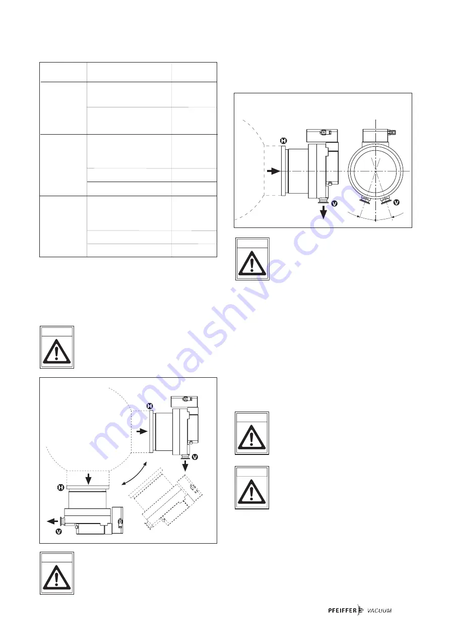
Directly flanging the pump
The turbopump can be flanged onto the vacuum chamber
vertically (0°) up to an angle of 90° maximum.
The fore-vacuum flange must always point
downwards.
CAUTION
Permissible installation positions for the turbopump
11
Vacuum chamber
20° 20°
Installation position with oil-sealed backing pump
11
Vacuum chamber
11
11
If the pump is being installed horizontally:
The fore-vacuum flange of the turbopump must be aligned
vertically downwards (maximum deviation ± 20°),
otherwise the turbopump could become dirty and the lubrica-
ting pump not properly function.
3.3. Connecting The Fore-Vacuum Side
Backing pump:
Vacuum pressure
≤
5 mbar
Recommendation:
Oil-Free Diaphragm Pump or Rotary
Vane Vacuum Pumps from the Pfeiffer
Vacuum range (note installation position,
turbopump, see Section 3.2.).
Connecting the backing pump
All connections of the fore-vacuum line: with the usual small
flange components or hose screw connections.
Be sure to conduct away the exhaust gases
from the backing pump. Do not reduce the free
cross section of the fore-vacuum flange with
following components.
The exhausted process gases and vapours can
represent a health hazard and can also be
environmentally damaging.
Comply with all gas manufacture's safety
instructions.
➡
With rigid pipe connections: fit a bellows in the connecting
line to reduce vibration.
➡
The electrical connection of the backing pump is made via
a relay box whose control line is connected to ”FV PUMP”
on the TC 600.
Please refer to Operating Instructions PT 0030 BN for details
on the relay box, backing pump and its installation.
WARNING
CAUTION


