PEZZOLATO TLC 1000 Instruction, Use And Maintenance Manual Download Page 38


CIRCULAR SAW TLC 800/900/1000/1200 vertical


34


1

B


2 5 0

0 0 0

A

C

2

Chapter 13  (control unity for cut) 

USE OF THE MACHINE


WARNING: 


No  one  can  pass  near  the  machine’s  working  area  with  the 
exception of the operator.


WARNING: 


Danger of wounds 

Wear  protective  gloves,  glasses,  caps  and  accident 
prevention shoes. 


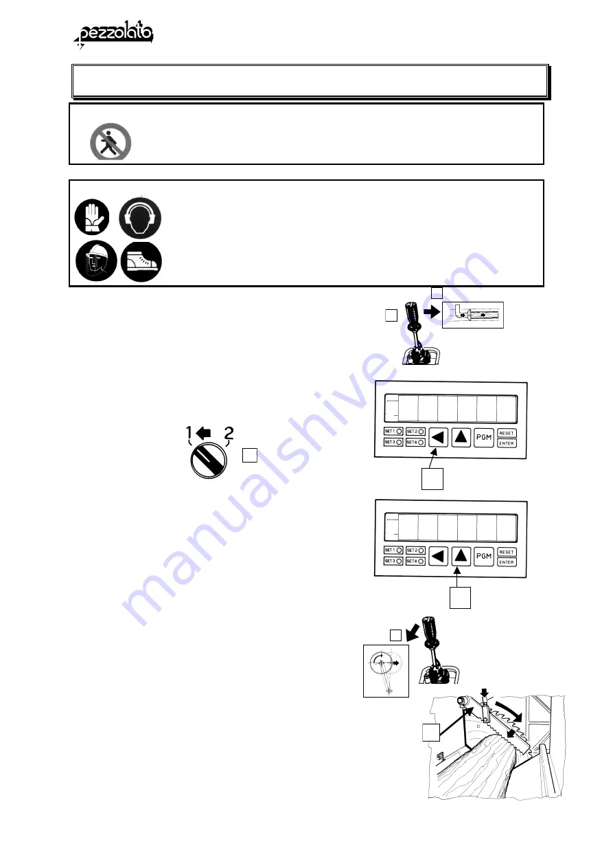
Move  the  lever  to  the  right  for  the 
advancement of the small plate. 
 
The  log  is  pushed  on  the  tunnel  until  the 
position  of  the  first  cut  and  noted  by  the 
photoelectric cell. The selector’s pilot light 
S light up. 


N.B.  When  the  cutting  selector’s  pilot 

light, pressing the key (B) on the 
display appear the log length. 
Pressing  the  key  (A)  on  the 
display  appear  the  measure  of 
the cut piece. 

N.B.:  if  the  selector’s  pilot  light  is 

switched 

off, 

position 

the 

selector on the direction 2. 


Push the lever to the position (1): you start 
the  cylinder  for  the  descent  of  the  arm 
which block the log (B) and, then, the saw 
disc advance. 
 
Leave again the lever for the return of the 
disc in the rest position. 
 
Operate in the same way for the following 
cuts for all the log length. 

0 0 0

0 0 2

B


S


Summary of Contents for TLC 1000

Page 1: ...INSTRUCTIONS USE AND MAINTENANCE MANUAL CIRCULAR SAW TLC 800 900 1000 1200 vertical wedge Issue 03 2004 Rev 01...

Page 2: ......

Page 3: ...2 Front door wood cutter side 10 5 3 Back protections 11 5 4 Emergency push buttons 11 06 Residual risks 12 6 1 Considerations about safety conditions and residual risks 12 07 Transport of the machine...

Page 4: ...ovement chain 64 15 5 Lubrication of the pusher s sliding chain 64 15 6 Adjustment of the pusher s cylinder 66 15 7 Adjustment of the tracer point s cylinder 66 15 8 Adjustment of the cylinder for the...

Page 5: ...They are written in cursive CAUTIONS This word is used for all the eventuality which can compromise the safety of the operator They are written in cursive and sometimes in black 1 1 Introduction N B...

Page 6: ...ot climb on the machine You can effect all the maintenance adjustment and replacement operations of the blade only after you have stopped the machine During the removing adjustment and replacement ope...

Page 7: ...ng the transport the machine can turn over So before to move the machine check the disconnectedness and the slope of the road which must not be more of 5 The maker has predisposed warning stickers and...

Page 8: ...ed replace them in accordance with the maker It is important that all operators had been conversant with the instruction manual In particular a equipment and working of the machine with the correct us...

Page 9: ...perings of the instructions manual and modifications of the machine after the delivery The maker reserve the copyrights of this manual and forbids the integral and partial divulgation in all forms pri...

Page 10: ...ad the manual for to know utilisation conditions of the machine work area of the operator instructions of starting operating transport setting up assembly and disassembly maintenance interventions tra...

Page 11: ...l safety rules 5 The maker denies any responsibility for eventual damage to the machine resulting from inappropriate use use by not competent operators use not conforming with the directions for use o...

Page 12: ...ding to the diameter of the shoe The material which comes out is pushed on a discharge conveyor belt You can discharge the pieces after the cut but you can not execute the operation of breaking TECHNI...

Page 13: ...LC 800 900 1000 1200 vertical Chapter 4 PRINCIPAL PARTS OF THE MACHINE AND THEIR POSITIONS LOG S LOCKING CYLINDER ELECTRIC PANEL CRADLE PUSHER BLOKS END OF STROKE WEDGE S DESCENT CYLINDER DISCHARGE BE...

Page 14: ...fixed carter C of perforated plate to protect the control side to prevent to the material which must be worked to come out and to prevent to the operator to have access at the cut and breaking areas...

Page 15: ...ections The back side of the machine where there are the transmission members and the engine is covered with fixed plate panels The panels must be removed only in case of maintenance when the engine i...

Page 16: ...ISKS CHAPTER OF REFERENCE Never remove protections when the machine is moving CHAPTER 4 Safety protections and devices Particularly you must not remove the closing fixed protections of the transmissio...

Page 17: ...ngine and take away the key from the control panel CHAPTER 13 Routine maintenance During the blade adjustment and replacement operations wear protection gloves to avoid possible accidents CHAPTER 12 U...

Page 18: ...king of the lifting cables If the lifting of the machine is effected with a crane the dimensions of the lifting cables must be adequate to the weight of the machine When the machine must be placed on...

Page 19: ...e to the weight of the machine connect the lifting cables as it is illustrated in the picture A pass a band under the structure of the pusher s cradle in the point which is indicated in the pictures A...

Page 20: ...d longitudinal sense positioning a spirit level L Check that the machine is in axle with the tractor Connect the cardan shaft C at the PTO of the tractor and at the shaft of enter of the machine Check...

Page 21: ...re that the door of the electric panel is closed Connect the two cables of exit of the electric panel at the battery of the tractor 12 V respecting the polarity black negative red positive WARNING Nev...

Page 22: ...le with 3 poles earth 4 x 16 for lengths less than 20 m It is obligatory the connection at earth It is obligatory the connection of the safety switch in the first part of the cable 380 V sensibility 0...

Page 23: ...ubricator group on the machine G N B To start the compressor you must consult the special manual you are equipped 8 3 Control of the air plant s filter lubricator assembly Check the oil level into the...

Page 24: ...ce as shoed in the picture Move the reversing gear in the position 1 Operate on the manual pump E for the descent of the back hydraulic feet G lifting the wheels from the floor Remove the plug S and u...

Page 25: ...t the machine is in axle with the tractor Connect the cardan shaft C to the tractor s PTO and to the shaft of entry of the machine A Check that the locking plugs are tripped N B The inclination of the...

Page 26: ...pulley Introduce with a pump for manual greasing the lubricant for bearings into the lay shaft s supports A B C as showed in the picture 8 6 Lubrication of the universal joint of the shaft pulley Intr...

Page 27: ...f inclination N B this operation must be executed by two operators 9 2 Adjustment of the conveyor belt tension Loosen the right and left turnbuckle s lock nut B Screw the right and left screw E to kee...

Page 28: ...PRESSURE GAUGE DISC C LEVER AT CLOCHE LOOK AT THE FUNCIONS AT THE NEXT PAGE D CONTROLS PUSH BUTTON PANEL LOOK AT THE FUNCIONS AT THE NEXT PAGE E DRIVE LEVER FOR CHAIN LOADER F WEDGE MOTION LEVER VERSI...

Page 29: ...PILOT LIGHT 4 ENGINE ON PUSH BUTTON BLACK 5 ENGINE ON PILOT LIGHT 6 ENGINE STOP PUSH BUTTON RED 7 TENSION PRESENCE PILOT LIGHT 8 INSERTED DISCONNECTED WOOD CUTTER 9 DISCONNECTED INSERTED MANUAL CENTER...

Page 30: ...W TLC 800 900 1000 1200 vertical 26 Chapter 10 CONTROLS MACHINE S CONTROL MEMBERS CONTROLS OF THE CLOCHE 1 ADVANCEMENT SAW DISC 2 ADVANCEMENT PUSHER 3 RETURN PUSHER 4 ADVANCEMENT WOOD CUTTER 5 ADVANCE...

Page 31: ...area Check that the machine has caution signs Check that the operator is able to use the machine the operator know well the use modality of the machine before to start it the operator know the safety...

Page 32: ...the circular saw Position the pusher P at a distance from the disc which is the same of the log s length to obtain The advancement A of the pusher is controlled by the lever at cloche C positioned at...

Page 33: ...caps and accident prevention shoes Position the log on the cradle Drive the lever C for the advancement of the pusher moving it to the right pos 2 The pusher push forward the log and stop itself at th...

Page 34: ...mity of the cloche C for the advancement of the pusher The piece is pushed in the wood cutter s cradle If the piece is not positioned correctly into the cradle you must open the door S and place it by...

Page 35: ...ccident prevention shoes Press the left push button at the extremity of the cloche C to start the wood cutter After to have cut the cylinder return in the rest position The cut material fall on the co...

Page 36: ...nds Wear protective gloves glasses caps and accident prevention shoes CUTTING OPERATIONS PREARRANGEMENT The machine can effect 2 cuts selected from the control panel with the selector S You can cut th...

Page 37: ...sses caps and accident prevention shoes CUTTING OPERATIONS Start the machine Position the cutting selector S in the position 1 Operate the lever at cloche to the right to advance the pusher and effect...

Page 38: ...t cut and noted by the photoelectric cell The selector s pilot light S light up N B When the cutting selector s pilot light pressing the key B on the display appear the log length Pressing the key A o...

Page 39: ...LARITY AND GUIDE OF THE PROGRAMMING 3 KEY PGM FOR THE ACCESS TO THE PROGRAMMING 4 KEY RESET ENTER FOR THE CONFIRMATION OF THE PROGRAMMED DATES 5 KEY UP TO CHANGE THE VALUE OF THE NUMBER SELECTED 6 KEY...

Page 40: ...B Press the key A the number which is flashing increase at every impulse from 0 to 9 example 251 To change the second number ten press the key B the second number flash To increase press the key A the...

Page 41: ...Press PGM 2 time appear c 000000 and the last number To have access at the programming you must introduce the code 9999 Plan the number 9 pressing the key A Press the key B the second number flash Pre...

Page 42: ...paragraph c 009999 and press the key ENTER to confirm On the display appear E x a m p l e t 0 0 0 0 1 5 t stop time 1 5 1 5 seconds To change the stop time press the keys A and B N B to pass at the s...

Page 43: ...following parameters 5 SLOWING DOWN PART r ALL 6 IMPULSES FOR ENCODER TOUR E 7 READING FOR ENCODER TOUR L 8 POSITION END OF STROKE RESET FCR 9 TUNNEL LENGHT Lt INTRODUCTION OF THE ACCESS CODE FOR THE...

Page 44: ...ENTER for the confirm on the display appear r ALL To plan the slowing down part press the keys A and B N B to pass at the successive programming press the key PGM 6 IMPULSES FOR ENCODER TOUR Press th...

Page 45: ...Press the key PGM on the display appear E x a m p l e F C R 0 0 0 0 To change the position press the keys A and B 9 TUNNEL LENGTH Press the key PGM on the display appear E s L T 0 1 0 0 0 To change th...

Page 46: ...Operate the lever at cloche for the return of the small plate making come back it at the end of stroke 3 Reset the computer pressing the micro switch of end of cut M look at the picture Operate the l...

Page 47: ...eys A and B E x a m p l e 0 0 0 5 0 0 Check that the real movement of the small plate correspond at the movement which is planed on the instrument Make a sign on the pusher starting point P Operate th...

Page 48: ...alibration after the last cut Cut the log example in pieces of 500 mm Measure the last cut piece Example 1 Last piece 480 mm The value of the parameter FCR is 500 480 20 mm Example 2 Last piece 520 mm...

Page 49: ...ter FCR Press for two times the key B the polarity indicator light up C Press the key A till when appear the sign 20 Press the key ENTER for the confirmation If the value is positive example 2 20 mm i...

Page 50: ...eter LT with the access code c 000212 Press the key PGM till when on the display appear LT and insert the part with the keys and Operate the lever at cloche C to the right to advance the pusher and ef...

Page 51: ...the display appear LTO 1000 Change the values in L T01020 with the keys A and B Press the key ENTER for the confirmation Example noted length bytheinstrument 1980 measured length 2000 Press PGM till w...

Page 52: ...OF THE WEDGE IN EXERCISE READING 3 seconds 3 KEY SET FOR THE ACCESS TO THE MAINTENANCE 4 KEY STOP NOT CONNECTED 5 KEY ENTER FOR THE CONFIRMATION OF THE PROGRAMMED DATES 6 NUMERIC KEYBOARD NUMBERS FROM...

Page 53: ...HE CODES CODE 3 HEIGHT CYLINDER AT REST Measure the distance between the log s support bottom pusher s cradle and the tracer point s bottom in the rest position look at the picture Go to the back of t...

Page 54: ...To insert the code 12 look at the preceding paragraph CODE 13 Measure the distance between the axle of the wedge at 6 ways X and the wedge base upper edge C CODE 14 Measure the distance between the ax...

Page 55: ...r guide A Go on the back side of the machine and open the housing box of the computer Press the key SET for 3 seconds until on the display appear BANDA 1 Press again the key SET appear BANDA 2 after t...

Page 56: ...split is upper respect the max diameter indicated it is automatically selected the cut at 6 ways B To insert the code 19 proceed as it is indicated before N B The codes 1 2 4 6 8 10 15 16 and from 20...

Page 57: ...WARNING The use of the programmed cut with computer is foreseen only for single pieces charge only one log Never use for the cut of sheaves of logs or for logs of irregular shape Risk of brake Before...

Page 58: ...ve gloves glasses caps and accident prevention shoes Predisposition To prearrange the machine for the cut with computer position the selector S on the position INS INSERTED The tracer point can take o...

Page 59: ...caps and accident prevention shoes Cutting operation computer Position the log on the cradle Start the lever C for the advancement of the small plate moving it to the right pos 2 The small plate push...

Page 60: ...ways N B program the max diameter measure for the cut at 4 ways on the numeric keyboard consult the chapter More than this part the cut will pass automatically at 6 ways After the cut press the right...

Page 61: ...ccident prevention shoes the piece is positioned in the cradle Press the left push button 4 on the extremity of the cloche C to drive the wood splitter After the cut the cylinder goes back in the rest...

Page 62: ...ng operation of the first piece start the lever C for the advancement of the small plate moving it to the right pos 2 The small plate push the log and stop itself at the fixed measure Push the lever i...

Page 63: ...e s working area with the exception of the operator WARNING Danger of wounds Wear protective gloves glasses caps and accident prevention shoes After the last cut the small plate return in the rest pos...

Page 64: ...t the current is disconnected electric engine Stop the tractor s engine PTO 15 1 Replacement of the blade N B Disconnect the current rotating the general switch in the position 0 Close the switch Loos...

Page 65: ...intenance operation to be sure that the current is disconnected electric engine Stop the tractor s engine PTO Unscrew the grain G Extract the worn disc and reassemble the new disc Screw again the grai...

Page 66: ...nsion of the angle set s belts N B Disconnect the current rotating the general switch in the position 0 Close the switch Disassemble the carter on the back side of the machine Check the tension of the...

Page 67: ...elts N B Disconnect the current rotating the general switch in the position 0 Close the switch Disassemble the carter on the back side of the machine Check the tension of the belts pressing with your...

Page 68: ...isconnect the current rotating the general switch in the position 0 Close the switch Check the tension of the pusher s movement chain C If it is loosed you must adjust it Loose the lock nut A Screw th...

Page 69: ...INT CYLINDER ENCODER 2 DRIVE CYLINDER LOG BLOCK ARM 3 DRIVE CYLINDER PUSHER 4 LUBRICATOR 5 FILTER 6 CONTROL SOLENOID VALVE CYLINDER PUSHER 7 CONTROL SOLENOID VALVE CYLINDER LOG BLOCK 8 CONTROL SOLENOI...

Page 70: ...JUSTING SCREW ADVANCEMENT SPEED ADJUSTING SCREW RETURN SPEED Adjust the screw A to have a rapid advancement The stroke is braked operating on the screw C Adjust the return speed operating on the screw...

Page 71: ...ustment of the cylinder s advancement speed is effected operating on the valve A positioned on the back panel to reduce the cut speed screw to increase the cut speed unscrew 15 9 Adjustment saw disc r...

Page 72: ...TO 15 10 Control and replacement of the feeding cable of the pusher s micro switch N B Disconnect the current rotating the general switch in the position 0 Close the switch Position the pusher at end...

Page 73: ...every 500 hours N B Disconnect the current rotating the general switch in the position 0 Close the switch Operations to execute for the replacement of the filter Stop the tractor s engine PTO N B pos...

Page 74: ...riodically the pressure and if it is necessary adjust it A CUTTING SPEED ADJUSTING VALVE ADJUSTABLE BY THE USAGER B WEDGE MAX PRESSION ADJUSTING VALVE MAX 70 BAR COMPUTER VERSION C PUSHER AUTOMATIC RE...

Page 75: ...H WOOD SPLITTER PRESSURE CONTROL GAUGE PRESSURE Adjusting valve max pressure primary pump wood splitter It is calibrate at 100 BAR WEDGE POSITIONING SOLENOID VALVE COMPUTER VERSION Adjusting valve ma...

Page 76: ...ated by the maker Do not modify the hydraulic system ADJUSTMENTS OF THE HYDRAULIC PLANT DISC EXIT ADJUSTING SOLENOID VALVE DISC RETURN ADJUSTING VALVE DISC EXIT SOLENOID VALVE EXCLUSION TAP DISC EXIT...

Page 77: ...all plate of the pusher must be stopped at a minimum distance of 5 mm from the saw disc To execute the adjustment loose the micro switch s locking screws M and move it on the slot A until to obtain th...

Page 78: ...electric connection must be made only by persons authorized The connection must be effected according to the national rules of the Country where the machine will be used All the interventions on the...

Page 79: ...ine there is a identification plate which indicate model serial number manufacturing date CEE Conformity marking Manufacturer s name and location Manufacterer s adress and telephone number Maximun pre...

Page 80: ...our machine make sure you follow all safety rules Dismantle and dispose of all sheaths flexible ducts and not metallic materials separately All metallic materials must be dismantled and assembled for...

Page 81: ...overed by a warranty for 12 months from manufacture defects The warranty starts from the date of machine start up the evidence given by the date of the shipment of the warranty coupon In any case the...

Page 82: ...al personnel performing the repair or must travel with the machine sent for repair PEZZOLATO S p A denies any responsibility for possible damage to persons or objects resulting from wrongful and willf...

Page 83: ...rtical Warranty Coupon Purchaser details Name and Family name Address Street Zip post Code City Tel Fax Reseller Head Office Address Street Zip post code City Tel Fax Machine denomination Equipment Se...

Page 84: ...__ _ _ _ _ _ _ _ _ _ _ _ _ _ _ Warranty Coupon Buyer Name and Family Name Address Street Zip post code City Tel Fax Reseller Head Office Address Street Zip post Code City Tel Fax Machine Denomination...

Reviews: