138
139
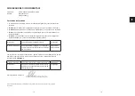
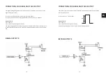
The power supply unit included must be used.
The conductance measurement may be strongly affected with third-party power supply units.
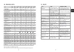
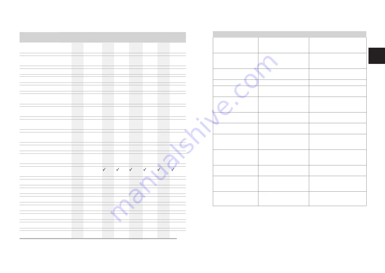
TYPE
PT-DA
1000
PT-DA
5000
PT-DA-CH
5000
PT-DB
1000
PT-DB
5000
PT-DBP
1000
PT-DBP
5000
PT-FCS
5000
PT-FCSD
5000
Supply voltage
in V DC / battery
3
2 x AA
3
2 x AA
3
2 x AA
3
2 x AA
3
2 x AA
24
24
24
24
Power consumption
in W, stand-by / max.
0,1 / 7 0,1 / 7 0,1 / 7 0,1 / 7
Ambient temp. in °C
5-40
5-40
5-40
5-40
5-40
5-40
5-40
5-40
5-40
Protection class
IP 32
IP 32
IP 32
IP 32
IP 32
IP 32
IP 32
IP 32
IP 32
Signal output in V / A
3 / 0,1 3 / 0,1 3 / 0,1
3 / 0,1 3 / 0,1 24 / 0,1 24 / 0,1 24 / 0,1 24 / 0,1
Pulse output
(1 pulse / ltr) V / A
3 / 0,1 3 / 0,1 3 / 0,1
3 / 0,1 3 / 0,1 3 / 0,1 3 / 0,1 3 / 0,1 3 / 0,1
Measuring range
in µS/cm
1 - 99
1 - 99
1 - 99
1 - 99
1 - 99 1 - 99
1 - 99
1 - 99
1 - 99
Connection thread
in DN / inch
15/G ½ 15/G ½ 15/G ¾
15/G ½ 15/G ½ 15/G ½ 15/G ½ 15/G ½ 15/G ½
max. operating temp.
in °C
30
30
30
30
30
30
30
30
30
max. inlet pressure in bar 4
4
4
10
10
10
10
10
10
Regulating range of
pressure reducer in bar
–
–
–
1,5 - 4 1,5 - 4 1,5 - 4 1,5 - 4 1,5 - 4 1,5 - 4
Integrated system
separator
–
–
–
Dimension b1 in mm
255
255
255
353
353
353
353
420
420
Dimension b2 in mm
383
383
383
480
480
480
480
544
544
Dimension h2 in mm
325
690
690
330
700
330
700
700
700
Dimension t in mm
58
58
58
67
67
67
67
67
67
Capacity in °TDS x litres 1000
5000
5000
1000
5000
1000
5000
5000
5000
max. flow rate in l/min 2
7
7
2
7
2
7
7
7
Weight in kg
3,4
6,3
6,3
5,2
8,1
5,2
8,1
8,5
8,5
10. TECHNICAL DATA
EN
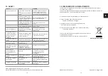
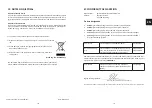
11. FAULTS
FAULT
CAUSE
REMEDIAL MEASURE
Flow rate too low or no
flow at all
System separator not
mounted in the flow direc-
tion
Install the system separator
in the flow direction (observe
arrow direction on housing)
Shut-off valves before or
after refilling combination
not fully open
Open the shut-off valves fully
Pressure reducer not set to
the desired outlet pressure Set outlet pressure
Integrated dirt trap dirty
Clean the dirt trap
Flow rate too low during
initial filling
Inlet pressure on the
pressure reducer too low
Increase outlet pressure during
initial filling
Drain valve opens for no
reason (no inlet pressure
fluctuations)
Non-return valve on inlet
side or drain valve dirty
Remove cartridge insert and
clean or replace it
Drain valve doesn't
close
Drain valve is dirty
Remove cartridge insert and
clean or replace it
Water escaping from
the spring cap
Diaphragm valve insert
defective
Replace valve insert
Set outlet pressure does
not remain constant
Nozzle or sealing ring of
the valve insert is dirty or
damaged (through-hole)
Replace valve insert
Conductance traffic light
turns red prematurely
Conductance briefly > 40
µS/cm
Reduce flow rate, in case of
automatic pressure holding
systems use PT-PS28000E
Display is blank
Power supply interrupted
Check battery seating, check
plug contacts of power adapter
Display error/display
doesn't react
Program may be "hung up"
Unplug power adapter for 10
secs. or briefly remove the
battery
Conductance display
shows E1
Conductance sensor defec-
tive (short-circuit)
Replace conductance sensor
Summary of Contents for PT-DA-CH5000
Page 72: ...142 143...

