136
137
EN
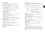
Function check/maintenance of the system separator
Installation and maintenance instructions for refilling combination
The maintenance of system separators may only be done by authorised technical personnel
•
Inspection interval: every 6 months
•
The maintenance check is to be carried out once per year
•
Execution by an installation company
Installation
The fitting must be installed horizontally (according to the arrow direction).
Drain facing downwards. Flush the pipe before installation.
Application
This refilling combination is suitable for the filling and refilling of heating systems.
The integrated filling assembly automates the heating system filling procedure. Two non-re-
turn valves and a pressure reducer are integrated in the filling assembly; the pressure reduc-
er ensures that the filling pressure of the system is correct.
Thanks to the BA system separator, which operates according to the three-chamber princi-
ple, this compact fitting prevents the back suction, backflow or back pressing of non-drinking
water from the heating system into the drinking water pipe.
Maintenance according to EN 806-5
Unscrew the cap of the filling assembly, remove the cartridge, check it and if necessary
replace it.
The system separator must be inspected and serviced at least once per year according to
EN 12729.
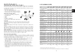
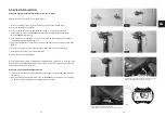
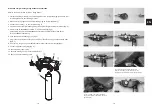
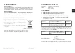
a. Close input (1) and output (1)
b. With the mini ball valves (2) in the closed state, remove the plug (4) and connect the input
tube of the test kit there
c. Remove the plug (3) and connect the output tube of the test kit there.
Open the mini ball valves again
d. Slowly open the bypass valve of the test kit until the drain valve begins to drip; note the
differential pressure. With the first droplet, the differential pressure must be over 0.14 bar.
e. Close the bypass valve again; the pressure increases to 0.4 bar (preset pressure); the car-
tridge begins to work again: the system separator is working correctly.
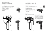
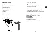
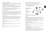
System separator type BA
1. Maintenance shut-off valves
2. Test valves
3. Plug
4. Plug
5. Filling assembly
6. Manometer with manome-
ter connection ¼"
2
3
5
1
6
4
2
1
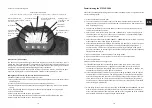
Refilling water monitoring/limitation
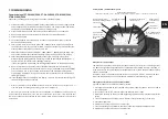
This setting defines the maximum permitted quantity of refilling water per week. In the case
of the PT-FCS / PT-FCSD, the acoustic signal and relay output are activated if the set value is
reached. The set value pulsates.
In the case of the mains variants PT-FCS / PT-FCSD, the supply of refilling water is interrupted
as well by closing the solenoid valve and the display lights up red.
By pressing OK, the water quantity is reset again, the signal is deactivated and the solenoid
valve is opened for 20 or 75 minutes (PT-FCS) respectively. The display lighting changes back
to white.
Setting range: 10 – 190 l/7d in steps of 10 l/7d or deactivated.
Display shows (---).
The refilling quantity monitoring must be deactivated when filling for the first time (see point
7. Commissioning). Factory setting deactivated. Display shows (--).
Refilling interval (PT-FCS only)
The refilling unit in the PT-FCS version is equipped with a normally closed solenoid valve
(NC). The solenoid valve opens after an adjustable interval of 48, 96 or 192 hours for 20 or
75 minutes respectively, so that filling water can automatically be added if necessary. It is
recommended to leave the factory setting of 192 hours unchanged in order to guarantee
the best possible volumetric measurement of the refilling water. Shorter intervals may be
necessary in the case of larger systems or a high refilling water requirement.
Conductance display
The conductance display (0 – 99 µS/cm) is only updated when a flow rate is measured. De-
pending on the permasoft size entered, the update only takes place between 0.3 and 1.5
litres in order to take into account the counterion effect of the mixed bed cartridge. At a
conductance of > 40 µS/cm, the colour of the display changes to red (PT-FCS/PT-FCSD).
In the case of a defective conductance sensor or a short-circuit, the display shows "E1".
Total water counter
The total water counter (1 to 99999 litres) registers the total filling water quantity since com-
missioning and cannot be reset.
Data storage
The set values of the parameters are saved one second after leaving the settings menu.
The total water quantity is saved once every 24 hours.
Cleaning
The electronics housing may only be cleaned with clean drinking water. All-purpose or glass
cleaners are not suitable.
Summary of Contents for PT-DA-CH5000
Page 72: ...142 143...

