118
119
PT-FCSD5000
PT-FCS5000
PT-FCS5000 and PT-FCSD5000
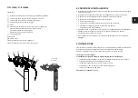
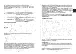
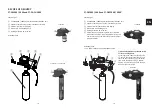
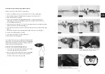
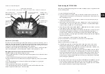
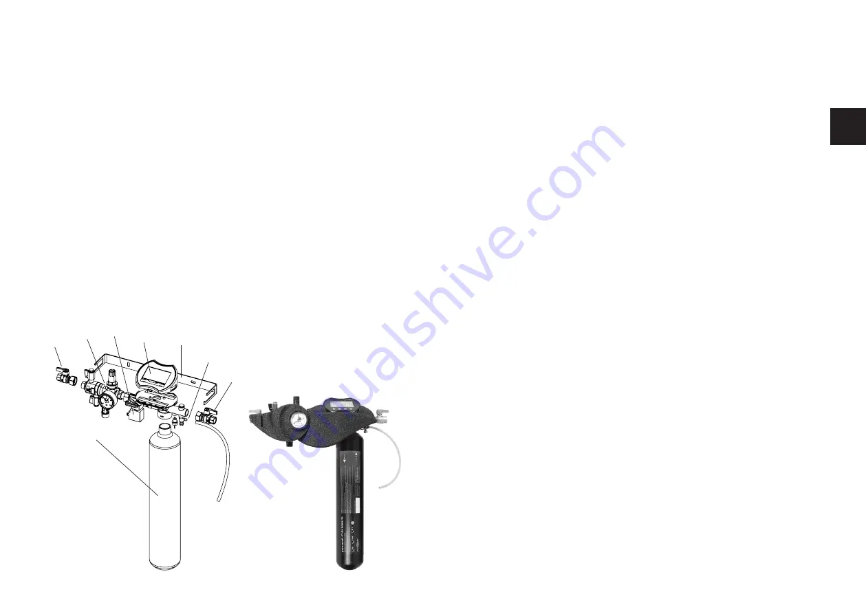
Consisting of:
①
PT-PS5000FD permasoft demineralisation unit
②
Separate shut-off valves on the inlet and outlet sides
③
Electronics with illuminated 4-inch display
④
Bleed valve with flushing hose
⑤
Holding bracket with screw set
⑥
System separator (according to EN 1717) type BA
with connection to HT pipe, integrated dirt trap
and non-return valve on the inlet side, pressure
reducer with manometer
⑦
Solenoid valve
Insulating shells
24 V power adaptor
Connection cable for solenoid valve
Connection cable 60 cm for relay / pulse output
⑥
①
②
②
③
④
⑤
⑦
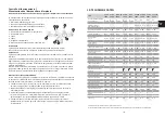
4. INSTALLATION CONDITIONS
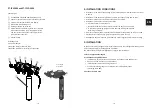
• Installation in the inlet of the heating system, maintaining a minimum distance of 0.3 m
to pumps
• Installation in the horizontal pipe with the drain connection facing downwards
• Installation location must be frost-proof and well ventilated
• Installation location must be easily accessible
• in order to simplify maintenance
• that the Manometer on the pressure reducer can easily be monitored
• to provide a smoothing length of 5 x DN after the refilling combination
(according to EN 806)
• A mains connection (230 V/50 Hz) must be available for the PT-DBP, PT-FCS or PT-FCSD
• Provide a drain connection (e.g. plastic pipe HT 40 or drain funnel)
• An adequate floor drain should be available to protect against possible water damage
5. INSTALLATION
To keep the volume of stagnant water as small as possible, the refilling combination should
be connected directly to the supply pipe if possible!
The rules of the Drinking Water Regulations apply to the installation.
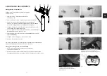
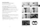
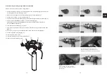
1. Flush the pipeline thoroughly
2. Install the heating filling station
• Installation in horizontal pipe with the drain connection facing downwards
• Observe the flow direction (arrow direction)
• Install without stress and bending moments
• Provide a smoothing length of 5 x DN after the refilling combination
(according to EN 806)
3. Position the drain pipe
EN
Summary of Contents for PT-DA-CH5000
Page 72: ...142 143...

