Assembly and Operation Manual
40
Attention!
During long-term and intensive operation of the turnstile with built-in readers, scratches and
scuff marks can appear on the glass surface either from access cards presentation (as well
as from wallets, bags, wristbands, watches, rings, etc.) or from cleaning substances with
abrasive inclusion.
Such damages are not a warranty case.
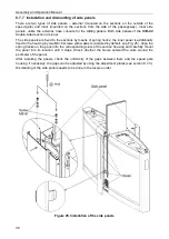
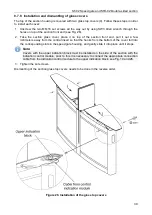
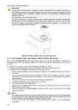
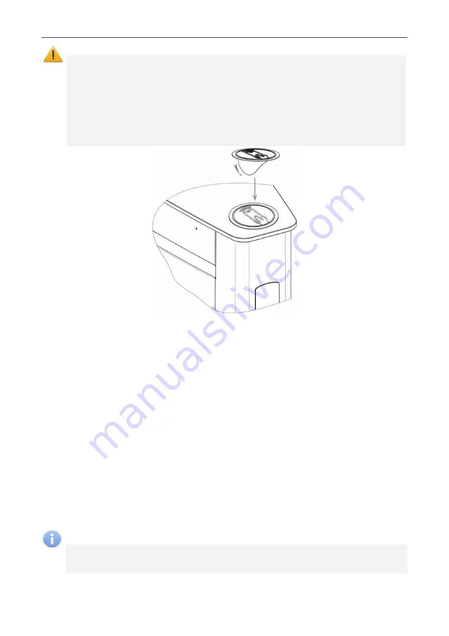
In order to prevent or remove such damages manufacturer has provided self-adhesive
rubber pads for card presentation areas (see Fig. 27). Moreover, consumer can use the
services of special companies providing professional glass polishing or purchase new
covers for replacement from PERCo.
Figure 27. Gluing rubber cover on glass top cover
8.7.9 The reduction of the passageway width of
STD-02.900
section
Design of the
STD-02.900
Double-sided section allows you to reduce the distance of departure of
the sliding panel from the housing to 280 mm in order to arrange the passageway with a width of
600 mm.
To do this, it is necessary to mount the sliding panel departure limiter:
1. Remove the sliding panel from the required side of the section (see sect.8.7.6).
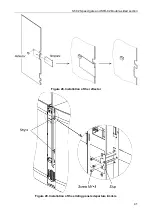
2. Stick the reflector supplied in the delivery set (see Fig. 28), so:
•
take a special template from the delivery set, install it in the sliding panel slot, as shown in
the figure;
•
remove the protective film from the adhesive surface of the reflector and stick it with a
strong push in accordance with the template, it is recommended to degrease and dry the
place of gluing;
•
remove the template, check the adhesion strength of the reflector.
•
Install the sliding panel into its place (see sect. 8.7.6).
•
Turn off the power of the speed gate.
•
Install the two supplied special stops on the section housing and secure each with three
M4×8 screws (see Fig. 29):
•
Install the jumper on the
XP3 "Mode"
connector of the motor drive board for this sliding
panel (see Fig. 30).
Note:
The sliding panel motor drive board is located under the glass top cover of the speed gate,
on the right side of the sliding panel and inside the gap of the section housing, see Fig. 6
(together with the control board from the
Master
section side).
•
Turn on and check the operation of the speed gate for each of the passageways
separately.

