background image

ST-02 Speed gate and STD-02 Double-sided section 


11 

The type of front end indication is selected during the speed gate  installation by switching the 

connection cable of the front end indication block to the corresponding connector of the indication 

control module (located under the speed gate top cover inside the housing, Fig. 19). By default, the 

connection cable is connected to the 

ARROW

 connector, which corresponds to the white arrow. It 

is necessary to remove the glass cover (3) in order to access the indication control module (see 

Fig. 26). 

5.2.3  RC-panel 

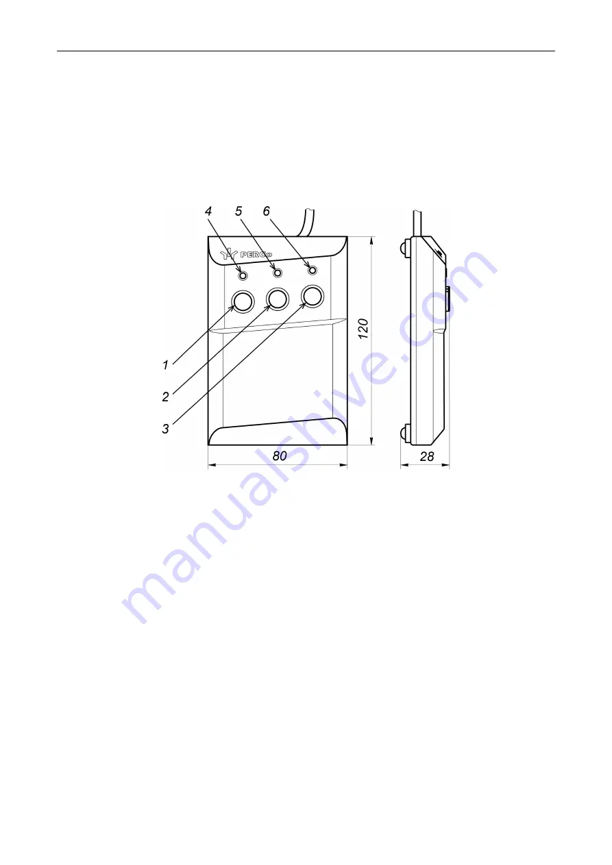
The RC-panel (11) is a small desktop device packed in a housing made of impact-resistant ABS 

plastic. The RC-panel is designed to send commands by an operator when controlling the speed 

gate manually. Overall view of the RC-panel is shown in Fig. 5. 


Figure 5. Overall view and overall dimensions of the RC-panel 

1, 2, 3 – 

LEFT

,

 STOP

,

 RIGHT

 buttons are used for control commands;  

4, 6 – 

"Left"

"Right" 

green LED indicators; 5 – 

"Stop" 

red LED indicator  

There are three buttons for sending commands on the RC-panel front panel. The middle 

STOP 

button is used to send the 

"Passage denial"

 command. Left and right buttons 

LEFT

RIGHT

 are 

used to send the command to open the passage in the selected direction. LED indicators of the 

passage direction status are located above the buttons. The red 

"STOP"

  indicator signifies that 

both directions of the passage are closed. The list of control commands and RC-panel indication 

for pulse and potential control modes are shown in Table 5 and Table 6.  

5.2.4  Control board 

The speed gate control board (Fig. 6) is located in one of the openings of the housing under the 

glass top cover of the 

Master

 section (see Fig. 20), the Board is covered by a metal cover with four 

screws with the aim of protecting from external actions. All input and output signals of the control 

board, with the exception of relay outputs that control additional remote indicators (

X4

 connector), 

are brought out to the contacts of the remote terminal block with DIN-rail (Fig. 7, sect.5.2.5). 
The control board is equipped with a microcontroller that processes incoming (

Unlock A

Stop

Unlock B

 and 

Fire Alarm

) control commands, monitors the optical sensors status and, based on 

the received data, generates commands for the sliding panels motor drive. 
Also, the microcontroller generates signals on the outputs of the control board: for RC-panel 

indication (outputs 

Led A

Led Stop

 and 

Led B

), for remote indication (outputs 

Light A

Light B

), the 

registration of the passage in the corresponding direction (

PASS A

  and 

PASS B

), the alarm 

(

Alarm

). Elements of the control board: 

Summary of Contents for ST-02 Series

Page 1: ...CERTIFICATE ST 02 Speed Gate STD 02 and Double Sided Section ...

Page 2: ...ST 02 Speed gate and STD 02 Double sided section Assembly and Operation Manual ...

Page 3: ...on details 22 8 2 Tools and equipment required for installation 22 8 3 Cable length 23 8 4 Installation procedure 23 8 5 Mounting surface layout 27 8 6 Speed gate wiring diagram 29 8 7 Installation and dismantling of the speed gate parts and elements 32 8 7 1 Dismantling and installation of the front end panel 32 8 7 2 Removing the section from the housing 33 8 7 3 Dismantling and installation of ...

Page 4: ...r of passage lanes it is necessary to purchase STD 02 double sided sections hereinafter double sided section Each double sided section allows you to organize one extra passage lane The double sided section has two main versions STD 02 600 for the organization of passageways with a width of 600 mm and STD 02 900 for the organization of passageways with a width of 900 mm In order to organize a check...

Page 5: ...h a width of 600 mm n number of ST 02 600 M S and STD 02 600 sections M number of passage lanes with a width of 900 mm m number of ST 02 900 M S and STD 02 900 sections Weight net ST 02 600 M ST 02 600 S section max 198 kg ST 02 900 M ST 02 900 S section max 224 kg STD 02 600 double sided section max 228 kg STD 02 900 double sided section max 230 kg sliding panel for ST 02 600 STD 02 600 max 9 kg ...

Page 6: ...ST 02 Speed gate and STD 02 Double sided section 5 Figure 1 Overall speed gate dimensions Figure 2 Overall dimensions of several passage lanes ...

Page 7: ...ction 2 4 1 2 STD 02 Double sided section Main equipment double sided section1 1 glass cover 2 side panel 2 filling glass 1 sliding panel 2 central insert 1 RC panel with cable 1 intersectional cables kit DC and CAN cables 1 jumper 3 FSS 5 board retainer 4 adjusting plate 1 mm 2 adjusting plate 1 5 mm 4 self adhesive rubber pad with mnemonic image 2 accessories for installation of the sliding pane...

Page 8: ...levels of the passage sensors are installed along the entire length of the speed gate passageway This allows you to track the position of the user within the passageway and also allows multiple users to be in the passageway at the same time who are passing in the same direction If necessary the number of passage lanes through the speed gate can be increased by installing STD 02 double sided sectio...

Page 9: ...tempered glass with a thickness of 8 mm 5 2 Device The speed gate design is shown in Fig 3 the double sided section is shown in Fig 4 The numbers of the parts in the text are shown in accordance with Fig 3 and 4 Figure 3 ST 02 overall view 1 sliding panel 2 filling glass 3 glass cover 4 central insert 5 upper indication block 6 side panel 7 front panel 8 front end indication block 9 DC connection ...

Page 10: ...d to the Master section via two DC and CAN connection cables 9 10 Each section has a sliding panel 1 and a fixed filling glass 2 In order to increase the number of passage lanes it is necessary to install double sided sections Each double sided section is also equipped with the RC panel 11 It has two sliding panels 1 on the Master side and Slave side Each sliding panel is driven by its electric dr...

Page 11: ...pped with indication blocks The sliding panel 1 is driven by a mechanism that is equipped with an electric drive and located inside the section There are two levels of passage sensors on the sides of the section the lower one 14 and upper one 15 are located under the plastic inserts and provide the passage control The ST02 30 771 control board hereinafter control board is installed under one of th...

Page 12: ...open the passage in the selected direction LED indicators of the passage direction status are located above the buttons The red STOP indicator signifies that both directions of the passage are closed The list of control commands and RC panel indication for pulse and potential control modes are shown in Table 5 and Table 6 5 2 4 Control board The speed gate control board Fig 6 is located in one of ...

Page 13: ...set to the position corresponding to this type of speed gate it is forbidden to change their position during operation Test 1 is not used Must be in OFF position during operation Test 2 is used to turn on the LED indication on the PCS boards By default the switch is in the OFF position which corresponds to the deactivated indication R1 is used to enable the Automatic opening in the selected direct...

Page 14: ...ection 10 Stop Control input passage denial 11 Unlock B Control input of B direction 12 Led A Indication output of direction A on the RC panel 13 Led Stop Output of passage denial indication on the RC panel 14 Led B Indication output of direction B on the RC panel 15 Sound RC panel audio output 16 Fire Alarm Emergency passage opening control input 17 GND 18 12V 12V output for additional devices 19...

Page 15: ...ith open collector output Emergency opening of the speed gate is carried out by sending a control signal to the Fire Alarm input The control signal is a low level signal released from the Fire Alarm contact relative to the GND contact Normally closed relay contact or circuit with open collector output can serve as a control element All control commands sent to the other inputs of the speed gate ar...

Page 16: ...of the control inputs Unlock A Unlock B and Stop in case there are corresponding signal levels on other inputs Note The active front of the signal corresponds to pressing the corresponding button on the RC panel WRC device The low level signal corresponds to the pressed button high level not pressed Potential control mode The mode is used to control the speed gate by using the ACS controller with ...

Page 17: ... passage direction User location in the passageway is monitored by passage sensors Note In order to prevent contact with the sliding panels the speed gate is equipped with the danger zone detection When the user is in this area the opening or closing of the sliding panels is blocked 5 After the user walks through the opened sliding panels he she gets into a safe zone the microcontroller of the con...

Page 18: ...nd unoccupied passageway in the Automatic opening in the selected direction mode direction the green indicator of the passage granting is lit the red indicator of the passage denial is lit from the opposite direction Pressing of the RC panel button or sending commands from the ACS controller for passage permission in the Automatic opening in the selected direction mode direction are ignored 2 The ...

Page 19: ...working place is located on the opposite side regarding Master section then for ease of operation it is necessary to swap the wires from the RC panel connected to the contacts Unlock A and Unlock B as well as Led A and Led B respectively see Table 2 Figure 10 Standard orientation of the RC panel towards the speed gate sections Table 2 Connection of the RC panel cable to the remote terminal block N...

Page 20: ...g contacts of the X2 connector Inputs of the ACS controller should be connected to PASS A PASS B and Common contacts of the remote terminal block or X3 connector of the control board Connection must be done in accordance with the speed gate wiring diagrams see Fig 17 and 18 5 4 Optional devices connected to the speed gate The following outputs are available on the speed gate control board for conn...

Page 21: ...NO normally open NC normally closed and C common outputs Connection to the outputs should be performed via corresponding contacts of the remote terminal block While passage granting indication in direction A B is on the LIGHT A LIGHT B relay of the corresponding direction is activated the coil is energized and normalized upon passage denial indication The fact of power supply to the relay coil can...

Page 22: ...f the speed gate should be carried out by persons who have fully studied this manual and briefed the safety instruction in compliance with the General rules of electrical and installation works Attention All installation work is carried out only when all power sources both main and backup emergency are switched off Use only properly functioning tools during the mounting procedures The speed gate s...

Page 23: ...y constantly following the instructions described in the section8 4 thus you do not have to repeat them again 8 1 Installation details Recommendations for the mounting surface preparations It is obligatory to mount speed gate sections on solid and even concrete not below 400 grade strength class B22 5 stone etc surfaces that have a thickness of more than 150 mm The mounting surface must be evened ...

Page 24: ... in section 8 6 Item numbers are shown in accordance with Fig 3 and 4 Attention The speed gate sections are heavy Moving of the speed gate sections should be carried out only with the use of the mounting tool use the special clamps located at the front ends of the section under the front end panels do not try to lift them by holding the glass top covers or other elements of the housing Installatio...

Page 25: ...s 5 Route all required cables in the cable channels see above p 4 6 Install the anchor sleeves in the holes so that they do not project above the floor surface 7 Unpack the Master section ST 02 M boxes No 1 and No 2 Note Box No 1 3 consists of a bottom that holds a section of the speed gate with transport bolts and an top box It is necessary to remove the fixed top box No 2 No 4 then unscrew the s...

Page 26: ...ocks 17 Take out the external connection cables from the inside of each section the sides of the section and connect them to the remote terminal block in accordance with the speed gate wiring diagram see Fig 17 Mount and secure the remote terminal block Carefully lay down the connected cables inside the housing of the section Note DC and CAN connection cables are connected to the remote terminal b...

Page 27: ...in the following order see sect 8 7 Install the front end panels 7 see sect 8 7 1 Fig 19 The panel with the front end indication block 8 must be mounted on the side of the section with the indication control module and the corresponding connection cable must connect the indication control module and the front end indication block see Fig 19 The connection cable connected to the ARROW connector of ...

Page 28: ...ST 02 Speed gate and STD 02 Double sided section 27 8 5 Mounting surface layout Figure 13 Layout for installation of the sections with the passageway width of 600 mm ST 02 600 STD 02 600 ...

Page 29: ...Operation Manual 28 Figure 14 Layout for installation of the sections with the passageway width of 900 mm ST 02 900 STD 02 900 Figure 15 Layout for installation of the sections with different width of the passageway ...

Page 30: ...ST 02 Speed gate and STD 02 Double sided section 29 8 6 Speed gate wiring diagram Figure 16 ST 02 and STD 02 wiring diagrams for the organization of a checkpoint with several N passage lanes ...

Page 31: ...Assembly and Operation Manual 30 Figure 17 Speed gate wiring diagram ...

Page 32: ...n 1 A3 RC panel 1 A41 Speed gate power supply 1 A51 Device for sending FireAlarm command 1 A61 A6 1 A6 2 ACS controller 1 A71 WRC device 1 A81 12V DC siren 1 A9 11 A9 21 Remote indication block 2 A101 Power supply for remote indicators 1 A111 RF1 and RF2 access card readers 2 1 DC connection cable 1 2 CAN connection cable 1 3 Jumper wire in case there is no FireAlarm device installed A5 Installed ...

Page 33: ...section 1 Slide the panel up along the front end side of the section in order to remove it from the hooks it is allowed to use a large flat screwdriver inserted into the slot at the bottom of the panel as a lever then carefully move it away from the section see Fig 19 for about 10 cm Be careful do not damage the connection cable 2 Disconnect the cable connector from the front end indication block ...

Page 34: ...th the SW4 Allen wrench see Fig 20 2 Remove the section from the housing The section is heavy move it by using two crowbars inserted into special eyelets from the front ends of the speed gate four people should carry out the procedure 3 Place the section on a flat steady surface Installation of the section on the housing must be done in reverse order Figure 20 Removing the section from the housing...

Page 35: ...void damage of the speed gate internal wiring You will first need to disconnect the internal wiring connectors if it becomes necessary to extend the removable part of the housing to a greater distance Connect the internal wiring connectors after you have routed the connection cables then slide with a jerk the removable part of the housing into place and tighten the mounting screws Be careful do no...

Page 36: ...tral insert from the delivery set mount it into place while observing the location of its grooves in accordance with the location of the sliding panels 2 Screw in the two M4 8 screws see Fig 22 with the washers by using PH2 Phillips screwdriver installed by default Dismantling of the central insert needs to be done in the reverse order Figure 22 Installation of a central insert ...

Page 37: ...wo M5 screws 4 that are located under the central insert on the sides by using S8 socket wrench see Fig 23 2 Carefully install the filling glass with curly cutouts on the sides into the gap that is located in the center of the central insert all the way in 3 Check that the glass is installed upright and align it if necessary Tighten the mounting screws Dismantling of the filling glass needs to be ...

Page 38: ...ut from the section housing It is also possible to tighten the bracket by using a long screwdriver or other suitable tools through the upper gap between the central insert and the housing without powering the speed gate on 2 Loosen the four M8 bolts on the top and bottom of the two fastenings of the sliding panel by using S13 open ended wrench see Fig 24 3 Hold the mounting bracket close to the ou...

Page 39: ... hooks the inner panel is additionally fixed to the housing by two M3 8 screws with washers installed by default see Fig 25 Align the spring hooks on the panel into the corresponding slots of the section housing and carefully mount the panel into its location until it stops Check whether the hooks entered the slots around the perimeter of the panel After installing the panels check the uniformity ...

Page 40: ...t out a few millimeters away from the central insert so that the hooks from the bottom of the cover fall into the corresponding slots in the speed gate housing and gently slide it into place until it stops Note Covers with the upper indication block must be installed on the side of the section with the indication control module prior to this it is necessary to connect the appropriate connection ca...

Page 41: ...mount the sliding panel departure limiter 1 Remove the sliding panel from the required side of the section see sect 8 7 6 2 Stick the reflector supplied in the delivery set see Fig 28 so take a special template from the delivery set install it in the sliding panel slot as shown in the figure remove the protective film from the adhesive surface of the reflector and stick it with a strong push in ac...

Page 42: ...ST 02 Speed gate and STD 02 Double sided section 41 Figure 28 Installation of the reflector Figure 29 Installation of the sliding panels departure limiters ...

Page 43: ...voltage and frequency specified in its datasheet 2 Turn on the power supply of the speed gate The speed gate sliding panels are automatically brought to the initial position 3 In the pulse control mode the command Passage denial is automatically sent in the potential Both directions are locked see Table 5 and Table 6 The speed gate is ready for operation 9 2 Pulse control mode Issuing of control c...

Page 44: ... selected direction Pressing of the LEFT button or RIGHT Red Stop indicator and green for the specified direction Left or Right are on Green arrow for a specified direction red cross for another direction The sliding panels open for a single passage in the specified direction and close after the passage The sliding panels open for a single passage in the specified direction and remain opened after...

Page 45: ...cle prevents the closing of the sliding panel three attempts to close sliding panels at intervals of 3 seconds will be made If the obstacle is not removed then the speed gate will switch to the Alarm mode In the Alarm mode the speed gate sliding panels can be moved apart manually which allows you to easily remove the obstacle from the passageway At the same time all three indicators of the RC pane...

Page 46: ...o 50 C at relative air humidity 80 at 15 C There should be no pair of acids alkalis and corrosive gases in the storage room Speed gate should be transported in the original package and in closed freight containers or other closed type cargo transport units in rail wagons containers closed cars holds airplanes etc It is not allowed to stack boxes during transportation and storage After transportati...

Page 47: ...e Unlock B contact low level on the Stop contact and the high level on Unlock A contact or active front is at Stop contact while a low level is at Unlock B and high level at Unlock A This command opens direction B until Passage denial command is received and direction A remains unchanged Free passage opened for free passage in both directions active front is at Unlock A contact low level at Unlock...

Page 48: ...PERCo Polytechnicheskaya str 4 block 2 194021 Saint Petersburg Russia Tel 7 812 247 04 64 E mail export perco com support perco com www perco com ...

Page 49: ...www perco com ...

Reviews: