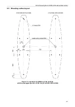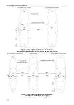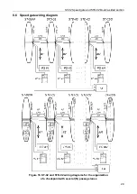
ST-02 Speed gate and STD-02 Double-sided section
19
When the
Fire Alarm
input is not used it is necessary to install a jumper wire between the
Fire
Alarm
and
GND
contacts of the control board. By default, this jumper is installed.
The speed gate switches to the
Fire Alarm
mode when the control signal is sent to the
Fire Alarm
input:
•
if the speed gate sliding panels were closed, then they will open in all operating modes and
remain open for free passage in both directions;
•
the green indicators of the passage granting will switch on in the flashing mode with a period
of 1.25 seconds on the upper indication blocks simultaneously for both directions;
•
all incoming control commands are ignored.
The speed gate will automatically switch to the operating mode in accordance with the control
commands after the control signal has been removed.
5.3.3 Operation from the ACS
The speed gate can be used as an operating device being a part of the ACS. The speed gate
provides the possibility to install built-in proximity card readers under the glass top cover.
The outputs of the ACS controller are connected to the
Unlock A
,
Stop
,
Unlock B
and
GND
contacts of the remote terminal block or, when installed inside the speed gate, directly to the
control board to the corresponding contacts of the
X2
connector. Inputs of the ACS controller
should be connected to
PASS A
,
PASS B
and
Common
contacts of the remote terminal block or
X3
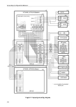
connector of the control board. Connection must be done in accordance with the speed gate
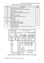
wiring diagrams (see Fig. 17 and 18).
5.4 Optional devices connected to the speed gate
The following outputs are available on the speed gate control board for connecting optional
devices:
•
PASS A, PASS B
- for connecting to the ACS controller inputs (see section 5.4.1).
•
ALARM
- for siren connection (see section.5.4.2).
•
Light A
and
Light B
-for remote indication blocks connection (see sect. 5.4.3).
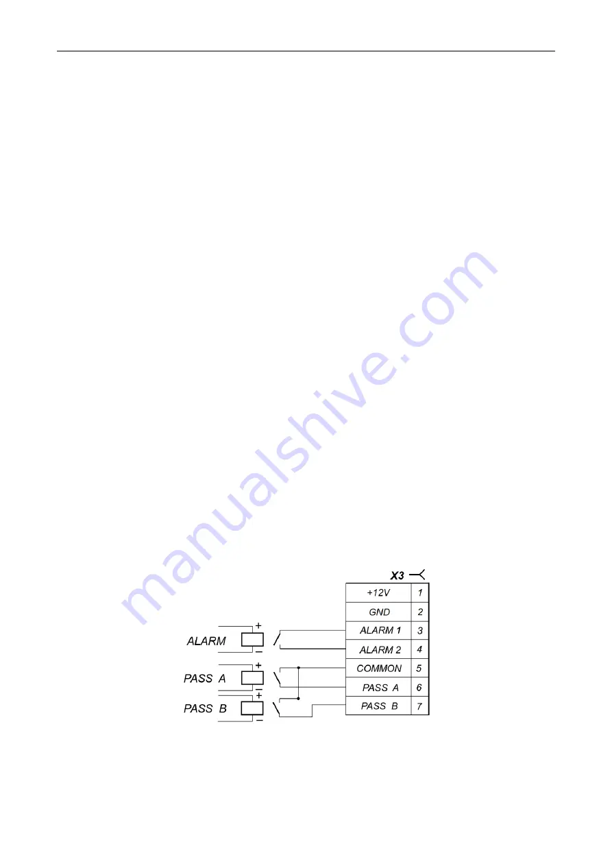
5.4.1 PASS Outputs
PASS A
,
PASS B
Relay outputs have normally closed contacts. The
Common
relay contact is not
connected to the negative terminal of the speed gate power supply. In normalized state the voltage
on the relay coil is not supplied.
The outputs are activated upon the passage registration in the specified direction. When the
voltage is supplied to the relay coil, the relay contacts close. The fact of supplying voltage to the
relay coil can be determined by the red LED on the control board near the corresponding relay (if
the control board features an installed jumper on the
XP3 (+12V)
connector).
Figure 11. Output stage for PASS A, PASS B and Alarm
Output stages - relay contacts (Fig. 11) with the following signal characteristics:
maximum commutating voltage DC .............................................................................. 42
V
maximum commutated current ............................................................................... 0.25 mA
closed contact resistance ........................................................................... max. 0.15
Ohms


