Assembly and Operation Manual
24
3.
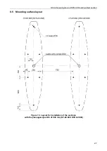
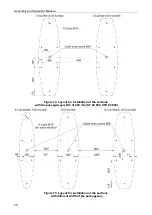
Mark and drill holes for anchor sleeves on the mounting surface for fastening speed gate
sections in accordance with the layouts, presented in Fig. 13-15 and in compliance with the
checkpoint project. Use a carbide drill to drill holes. The drilling depth for the standard PFG
IH10 anchors should be 65 mm.
Note:
It is acceptable to use the base of the section as a template for marking holes. To do this,
you must first unpack the section and remove its base (see below, Section 7).
Attention!
It is necessary to leave a gap of at least 70 mm between the side of the section and the wall
in order to ensure ease of installation of the speed gate sections.
4.
Prepare the floor cable channels:
•
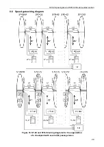
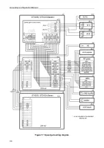
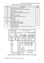
channels for cable connection from external devices – power supply (12), RC-panel (11)
or ACS-controller,
Fire Alarm
(13) device and other optional equipment- to the input holes
of the
Master
section and to the input of the double-sided sections;
•
channels that connect holes for leading in cables of opposite sections (sides of double-
sided section) of one passage lane – for leading in DC (9) and CAN (10)
cables, and also for installation of built-in readers – cable for reader connection from the
Slave
section to the ACS controller (RF cable on layout in Fig. 16 and Fig. 18).
Attention!
Passageways that are limited by one-sided sections and/or sides of double-sided sections
are separate functional devices that are not directly connected to each other.
The
Master
and
Slave
sides of one double-sided section are electrically independent as
they belong to different passage lanes.
5.
Route all required cables in the cable channels (see above, p.4).
6.
Install the anchor sleeves in the holes so that they do not project above the floor surface.
7.
Unpack the
Master
section (
ST-02/M
, boxes No.1 and No.2).
Note:
Box No. 1 (3) consists of a bottom that holds a section of the speed gate with transport
bolts, and an top box. It is necessary to remove the fixed top box No. 2 (No. 4), then
unscrew the screws around the perimeter of the bottom, and separate the top box. It is
enough to unscrew the screws from one of the side covers of the box so the top box could
be easily removed.
In order to take the section off the bottom of the shipping box:
•
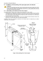
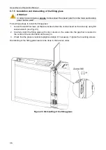
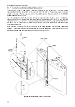
Dismantle the front end panels (7) (see sect.8.7.1, Fig. 19). Be careful, do not damage
the connection cable of the front end indication block (8)!
•
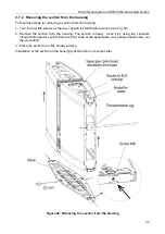
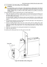
Remove the section from its base (see Fig. 20) and place it on a flat, stable surface.
Move the section by using two crowbars inserted into special eyelets located on the front
ends of the speed gate, four people should carry out the procedure!
•
Unscrew the base from the bottom of the box and remove it.
8.
Install base of the
Master
section on the sleeve anchors. Pull out the ends of all cables
connected to the section through the cable entry hole located on the base of the
Master
section.
9.
Secure the base of the
Master
section on the mounting surface by using six M10 anchor
bolts and washers.
10. Install the
Master
section on the base by pulling its connection cables inside. Secure the
section to the base with the four M8 set screws by using the SW4 Allen wrench (see Fig. 20).
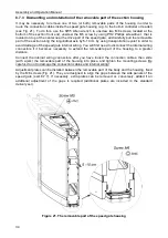
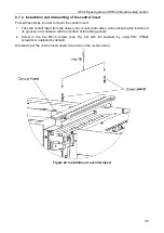
If necessary, it is possible to disconnect and extend one or two removable parts of the
housing along the X-axis for more convenient cabling inside the housing section (see
1
Included in the standard delivery set.


