


8
PN957 (25-06-20)
PUMP CONNECTIONS
If the Pentair Pentek Intellidrive® Constant Pressure Pump
Controller is used with above ground motors (3-phase only) not
rated for Variable Frequency Intellidrive use, maximize motor
life by limiting lead length to 25 ft. Refer to the pump’s owner’s
manual, the National Electrical Code, and local codes for proper
wire size.
The output of the Intellidrive is single phase (2-wire or 3-wire)
or 3-phase, depending on motor selection during startup. The
output power terminals (motor wire connections) are located
on the lower right side of the Intellidrive and are labeled R (Red),
Y (Yellow), and B (Black).
To select the wire size, multiply the wire length by 0.95 and then
refer to the pump owner’s manual, the Nation Electric Code, and
local codes for proper wire size.
NOTE:
Regardless of owner’s manual, wire LENGTH may not
exceed 1000 ft. (305 M).
NOTE:
2-wire 1-phase connect to Y+B, not R+B.
FAN
The Intellidrive uses a thermostatically controlled internal
fan which operates automatically when necessary to cool the
Intellidrive components.
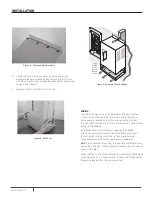
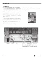
INSTALLATION
Figure 7 - Keyboard Functions
5999 0509
Terminal
Removable
(pull down)
01+ 01+ I1+ I1- I2+ I2- V+ V- AI+ AI- P N SD CARD
Transducer Cable
Connections
Submersible Motor: 3-Ph./ 3-W. 1-Ph., follow colors as above.
Submersible Motor: 1-Ph./ 2-W., connect to Y and B, any order.
Above-Ground Motors: L1 to R, L2 to Y, L3 to B; verify rotation.
Output
Ground Screw
Input Power
Connections
Red
Yellow
Black
Output Ground
Input
Ground
6539 0412
Motor Connections
Red to AI+
Black to AI–
Green Cable Shield/Screw
Terminal
Removable
(pull down)
Input
Ground Screw
Figure 8 - Basic Wiring Connections


