


6
PN957 (25-06-20)
INSTALLATION
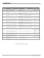
CIRCUIT BREAKER AND WIRE SIZES
Motor
Volts
Motor HP
Input Wire
Size
Circuit Breaker*
Generator (kVA)**
2-wire
230
1/2
14
15
2.2
230
3/4
12
15
3.1
230
1
12
20
4.4
230
1-1/2
10
25
5.3
3-wire
230
1/2
14
15
2.3
230
3/4
12
15
3.0
230
1
12
15
3.5
230
1-1/2
10
25
5.3
230
2
10
25
5.8
3 phase
230
1/2
14
15
2.1
230
3/4
14
15
2.8
230
1
12
15
3.4
230
1-1/2
12
20
4.4
230
2
10
25
5.5
230
3
10
30
7.3
230
5
6
50
12.6
* With properly-sized circuit breakers, the Intellidrive is protected from short circuit on the input and the output. There is no
risk of fire or electrical shock due to a short circuit. The Intellidrive has NEC Class 10 overload protection.
** Minimum 240V generator size.
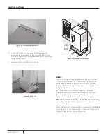
Figure 3 - Seperate Cover And Back
INSTALLATION MOUNTING
To mount the Pentair Pentek Intellidrive® Constant Pressure
Pump Controller:
1. First, remove the cover by backing out screw at bottom of
front cover.
2. Push on backplate with thumbs while pulling the cover
toward you with index fingers, creating a gap (Figure 3 and
4).
3. Pull the bottom of the cover towards you. Lift up on cover
and remove (Figure 5).
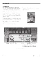
4. With the cover removed, permanently mount the Intellidrive
using the top slotted hole, plus either the three bottom
holes (for flat surface mounting) or the center bottom hole
(for attaching to a post or stud). See Figure 6.
5. Ensure the Intellidrive’s ventilation holes are not blocked
and there is enough space around it to allow free air flow
(minimum 3” clearance on top, bottom, and sides). See
Figure 6. Once the Intellidrive is mounted, electrical wiring
can be connected.


