background image

41

Chapter 5: VIA VT8237 SATA RAID Setup Guide

3 Select task and press <Enter>. The screen returns to Create Array menu

items. From this point, you may choose to auto-configure the RAID
array by selecting Auto Setup for Data Security or manually configure
the RAID array for mirrored sets. If you want to manually configure the
RAID array continue with next step, otherwise, proceed to step #5.

4 Select Select Disk Drives, then press <Enter>. Use arrow keys to select

disk drive/s, then press <Enter> to mark selected drive. (An asterisk is
placed before a selected drve.)

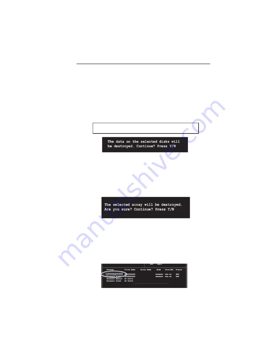
5 Select Start Create Process and press <Enter> to setup hard disk for

RAID system. The following confirmation message appears:

Press “Y” to confirm or “N” to return to the configuration options.

The same confirmation message appears when
the Auto Setup for Performance option is selected.

Delete Array

1 In the VIA RAID BIOS utility main menu, select 

Delete Array

 then

press the <Enter> key. The focus is directed to the list of channel used for
IDE RAID arrays.

2 Press the <Enter> key to select a RAID array to delete. The following

confirmation message appears.

Press “Y” to confirm or “N” to return to the configuration options.

Select Boot Array

1

In the VIA RAID BIOS utility main menu, select Select Boot Array then

press the <Enter> key. The focus is directed to the list of channel used
for IDE RAID arrays.

2

Press the <Enter> key to select a RAID array for boot. The Status of the

selected array will change to Boot. Press <ESC> key to go return to
menu items. Follow the same procedure to deselect the boot array.

Summary of Contents for P53G Series

Page 1: ...tel Corporation Microsoft MS DOS and Windows 2000 XP Vista are registered trademarks of Microsoft Corporation AMI is a trademark of American Megatrends Inc It has been acknowledged that other brands o...

Page 2: ...vices 13 Install Other Devices 15 Expansion Slots 18 Chapter 3 BIOS Setup Utility 20 Introduction 20 Running the Setup Utility 20 Standard CMOS Setup Page 21 Advanced Setup Page 22 Advanced Chipset Se...

Page 3: ...ogue box shown as below pop out warning you this software has not passed Windows Logo testing to verify its compatibility with Windows XP Please rest assured that our RD department has already tested...

Page 4: ...mplementing Universal Serial Bus Specification Revision 2 0 and is compliant with UHCI 1 1 and EHCI 1 0 It supports High Definition Audio Codec and provides Ultra DMA 133 100 66 function It has one PC...

Page 5: ...m Memory Controller Support DDR2 SDRAM with up to maximum memory of 4 GB PCI Express Graphics Interface Support One PCI Express x16 port PCI Bus Interface Support PCI Revision 2 3 Specification at 33M...

Page 6: ...udio Codec ADCs support 44 1k 48k 96k sample rate High quality analog differential CD input Meet Microsoft WHQL WLP 3 0x audio requirements Direct Sound 3DTM compatible BIOS Firmware This motherboard...

Page 7: ...on cable The Software support CD Optional Accessories You can purchase the following optional accessories for this motherboard The Extended USB module The CNR v 90 56K Fax Modem card The SerialATAcabl...

Page 8: ...Install this motherboard in a system chassis case Connect any extension brackets or cables to headers connectors on the motherboard Install peripheral devices and make the appropriate connections to h...

Page 9: ...IR1 Infrared header 10 PANEL1 Front panel sw itch LED header 11 CLR_CMOS Clear CMOS jumper 12 USB3 4 Front Panel USB headers 13 USBPWR_F2 Front Panel USB Pow er Select Jumper 14 FDD Floppy disk drive...

Page 10: ...M port to connect serial devices such as mice or fax modems COM1 is identified by the system as COM1 VGA Port Use the VGA port to connect VGA devices LAN Port optional Connect an RJ 45 jack to the LAN...

Page 11: ...che memory CPU Installation Procedure Follow these instructions to install the CPU B Unload the cap Use thumb forefinger to hold the lifting tab of the cap Lift the cap up and remove the cap completel...

Page 12: ...DDR2 SDRAM offers greater bandwith and density in a smaller packahe along with a reduction in power consumption In addition DDR2 SDRAM offers new features and functions that enable a higher clock rate...

Page 13: ...re is a notch on the DIMM socket that you can install the DIMM module in the correct direction Match the cutout on the DIMM module with the notch on the DIMM socket 3 Install the DIMM module into the...

Page 14: ...ability after clearing CMOS we recommend users to enter the main BIOS setting page to Load Optimal De faults and then Save Changes and Exit BIOS_WP BIOS FLASH PROTECT Jumper Use this jumper to set the...

Page 15: ...sure your case has an I O cover plate matching the ports on this motherboard Install the motherboard in a case Follow the case manufacturer s instructions to use the hardware and internal mounting po...

Page 16: ...r on the motherboard Pin Signal Pin Signal 1 SPDIFOUT 2 5VA 3 KEY 4 GDN SPDIFO1 S PIF Out Header S PDIF Sony Plilips Digital Interface is a standard audio transfer file format and allows the transfer...

Page 17: ...ps Personal Digital Assistants PDAs and other computers 1 Locate the infrared port IR1 header on the motherboard 2 If you are adding an infrared port connect the ribbon cable from the port to the IR1...

Page 18: ...LPT1 Onboard parallel port Header This header allows the user to connect to the printer scanner or devices Pin Signal Pin Signal 1 STROBE 2 PD0 3 PD1 4 PD2 5 PD3 6 PD4 7 PD5 8 PD6 9 PD7 10 ACK 11 BUS...

Page 19: ...Master device connects to the end of the cable Install the device s and connect power from the system power supply Use the cable provided to connect the device s to the Primary IDE channel connector...

Page 20: ...in Signal 1 CD IN L 2 GND 3 GND 4 CD IN R Analog Audio Input Connector If you have installed a CD ROM drive or DVD ROM drive you can connect the drive audio cable to the onboard sound system When you...

Page 21: ...18 Motherboard User s Guide Expansion Slots This motherboard has one PCI Ex16 one PCI Ex1 and two 32 bit PCI slots...

Page 22: ...e Specification revsion 1 0a Follow the steps below to install an PCI Express CNR PCI expansion card 1 Locate the PCI Express CNR or PCI slots on the motherboard 2 Remove the blanking plate of the slo...

Page 23: ...me hardware installed in or connected to the motherboard such as the CPU system memory disk drives etc Running the Setup Utility Every time you start your computer a message appears on the screen befo...

Page 24: ...an ATAPI device with removable media e g a ZIP drive or an LS 120 select Floptical If you have already changed the setup utility press F10 to save those changes and exit the utility Press F1 to displ...

Page 25: ...s item determines if the NumLock key is active or inactive at system start up time APIC Mode This item allows you to enable or disable the APIC Advanced Programmable Interrupt Controller mode APIC pro...

Page 26: ...boot sequence from the available devices CMOS Setup Utility Copyright C 1985 2005 American Megatrends Inc Removable Drives Move Enter Select Value F10 Save Esc Exit F1 General Help F9 Optimized Defaul...

Page 27: ...stem searches all other possible locations for operating system if it fails to find one in the devices specified under the First Second and Third boot devices Press Esc to return to the main menu page...

Page 28: ...nabled USB Function For DOS Enabled OnBoard Floppy Controller Use this item to enable or disable the onboard floppy disk drive interface Serial Port1 2 Address Use this item to enable or disable the o...

Page 29: ...S Enable this item if you plan to use the USB ports on this motherboard in a DOS environment Use this item to enable or disable the onboard Audio controller Use this item to enable or disable the boot...

Page 30: ...system will be awakened from power saving modes when activity or input signal of the specified WOL device is detected Resume On PS 2 Mouse This item enables or disables you to allow mouse activity to...

Page 31: ...voltages temperatures and fan speeds CMOS Setup Utility Copyright C 1985 2005 American Megatrends Inc PC Health Status Vcore 1 296V Vdimm 1 592V Vcc5V 1 296V CPU FAN Speed 1962RPM CPU Temperature 162...

Page 32: ...uency Voltage Control Page This page helps you to set the clock speed and system bus for your system The clock speed and system bus are determined by the kind of processor you have installed in your s...

Page 33: ...tings This option opens a dialog box to ask if you are sure to install optimized defaults or not You select OK and then Enter the Setup Utility loads all default values or select Cancel and then Enter...

Page 34: ...p Utility and exit the Setup Utility When the Exit Without Saving dialog box appears press Y to discard changes and exit or press N to return to the main menu Change Supervisor Password You can select...

Page 35: ...depending on your operating system If your operating system is Windows 2000 XP Vista it will automatically install all the drivers and utilities for your motherboard Installing Support Software 1 Ins...

Page 36: ...ReadMe brings you to the Install Path where you can find out path names of software driver Auto Installing under Windows 2000 XP Vista If you are under Windows 2000 XP please click the Setup button t...

Page 37: ...tup Procedure users should use one of the following two methods to install the driver after the system restart Method 1 Run Reboot Setup Windows Vista will block startup programs by default when insta...

Page 38: ...35 Chapter 4 Software Applications Follow these instructions to Disable Vista UAC function 1 Go to Control Panel 2 Select Classic View 3 Set User Account...

Page 39: ...rting the support CD ROM 2 A software menu appears Click the software you want to install 3 Follow onscreen instructions to install the software program step by step until finished 4 Select Turn User...

Page 40: ...data in the other drive This RAID configuration provides data protection and increases fault tolerance to the entire system JBOD Just a Bunch of Drives Also known as Spanning Two or more hard drives a...

Page 41: ...stall the Serial ATA hard disks into the drive bays 2 Connect one end of the Serial ATA cable to the motherboard s primary Serial ATA connector SATA1 3 Connect the other end of Serial ATA cable to the...

Page 42: ...ray menu options RAID 0 for performance 1 Select the second option item Array Mode then press the Enter key The RAID system setting pop up menu appears 2 Select RAID 0 for performance from the menu an...

Page 43: ...t the second option item Array Mode then press the Enter key The RAID system setting pop up menu appears 2 Select RAID 1 for data protection from the menu and press Enter Select next task from pop up...

Page 44: ...ears Press Y to confirm or N to return to the configuration options The same confirmation message appears when the Auto Setup for Performance option is selected Delete Array 1 In the VIA RAID BIOS uti...

Page 45: ...is option is useful for identifying same model disks Duplicate Critical RAID 1 Array When booting up the system BIOS will detect if the RAID 1 array has any inconsistencies between user data and backu...

Page 46: ...ts a broken RAID 1 array but there is no spare hard drive available for rebuilding the array BIOS will provide several operations to solve such 1 Power off and Check the Failed Drive This item turns o...

Page 47: ...sing a hard drive the channel column will be activated Highlight the target hard drive and press Enter a warning message will appear Press Y to use that hard drive to rebuild or press N to cancel Plea...

Page 48: ...rs on Windows XP Setup screen press the Enter key 5 Press Enter to continue with installation or if you need to specify any additional devices to be installed do so at this time Once all devices are s...

Page 49: ...g system This version of VIA SATA RAID Utility contains the following key features Serial ATA RAID driver for Windows XP VIA SATA RAID utility RAID0 and RAID1 functions Insert the supported CD and cli...

Page 50: ...he installation Using VIARAID Tool Once the installation is complete go to Start Programs VIA raid_tool exe to enable VIA RAID Tool After the software is finished installation it will automatically st...

Page 51: ...roller or disk drives The available features are as following It means that VT8237 SATA RAID only has the feature of monitoring the statuses of RAID 0 and RAID 1 View by Controller View by Devices Vie...

Page 52: ...49 Chapter 5 VIA VT8237 SATA RAID Setup Guide You may also use the same or button to view the statuses of Array 0 RAID 1 Click on the plus symbol next to Array 0 RAID 0 to see the details of each disk...

Page 53: ...50 Motherboard User s Guide Click on the plus symbol next to Array 0 RAID 1 to see the details of each disk...

Reviews: