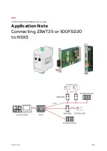
4.0 INSTALLATION
Once the Model 2703-X21 is properly configured, it is ready to
connect to your system. This section tells you how to properly connect
the Model 2703-X21 to the G.703 network and terminal device
interfaces.
4.1 CONNECTION TO THE G.703 NETWORK
The Model 2703-X21 supports 2.048 Mbps communication over an
unstructured G.703 network. Both 120 ohm twisted pair and 75 ohm
coax interfaces are provided on the rear panel of the Model 2703-X21
(see Figure 6, below). Be sure the unit is configured properly to operate
in either 120 ohm or 75 ohm mode, and that the network connection is
grounded appropriately (see Section 3.0).
4.1.1 Twisted Pair (120 OHM) Connection
The Model 2703-X21 is equipped with a single RJ-45 jack for
connection to a 120 ohm twisted pair G.703 network interface. The
pinout of this jack is as follows:
RJ-45 Pins
SIGNAL
1 & 2 . . . . . . . . . . . . Receive pair (from network)
3. . . . . . . . . . . . . . . . Shield reference point
4 & 5 . . . . . . . . . . . . Transmit pair (to network)
6. . . . . . . . . . . . . . . . Shield reference point
7. . . . . . . . . . . . . . . . Not used
8. . . . . . . . . . . . . . . . Not used
4.1.2 Dual Coax BNC (75 OHM) Connection
In addition to the 120 ohm twisted pair connection, the Model 2703-
X21 is equipped with dual female BNCs (TX and RX) for connection to
a 75 ohm dual coax G.703 network interface. The outer conductor of
the coax cables is isolated from system earth ground.
4.2 CONNECTION TO THE TERMINAL DEVICE
The Model 2703-X21 is wired as a DCE, and–when configured
properly–supports communication with an X.21 DTE device. The Model
2703-X21 is equipped with a DB-15 female connector and uses a
standard X.21 patch cable, wired
straight through. If you wish to
construct your own terminal adapter cable, please consult the pinout
diagram in Appendix B.
4.3 CONNECTION TO THE POWER SOURCE
As described in Section 3.3, the Model 2703-X21 is available with
three power supply options: two AC and one DC. The two AC power
supply options (Standard and Universal) use a female IEC power cord
interface, for which Patton can supply various domestic and
international power cords. Please refer to Appendix C for specific
Patton part numbers when ordering power cords. The DC power
supply option uses a 3-pin terminal strip interface (Note: Please refer
to the Model 2703-X21 Service Manual for DC power supply wiring
instructions).
11
12
Network
DTE Interface
Figure 6. Model 2703 rear panel
(Model 2703-X21-DC has terminal strip)