background image

3.0  CONFIGURATION

The Model 2070 is easy to install and is ruggedly designed for

excellent reliability.  The following instructions will help you set up and
install the Model 2070 properly.  

3.1.  OPENING THE CASE

To use the Patton Model 2070, you must first configure the unit for

your application.  To do so, first open the case by inserting a flat head
screw driver into an open slot on either side of the case, as in Figure 1. 

Twist the screw driver head slightly and the top half of the case will

separate from the lower half, as in Figure 2. You now have access to
the internal switches used to configure the unit.

After opening the case, please refer to the section that pertains to

your unit for configuration details.

5

Figure 1. How to Use a Small Flathead Screwdriver to Begin to Open the Model 2070 Case

Figure 2: How to Use a Small Flathead Screwdriver to Finish Opening the Model 2070 Case   

Notice!

The RJ-45 G.703 port of the Model 2070  is intended

to connect to telecommunication network voltage (TNV)
circuits which may carry dangerous voltages.  Therefore the
power and network cables must be disconnected prior to
switch and jumper configuration.  

3.2  CONFIGURATION  (MODEL 2070/Ax  V.24 VERSION)

The Model 2070/Ax  uses a mini DIP switch package and jumper

strap that allow configuration to a wide range of applications.  The
switch and the jumper are located on the bottom side of the PC Board.
Follow the instructions below to configure the 2070/Ax (V.24 Version).
See Section 3.3 to configure the Model 2070/Cx (V.35 Version) or
Section 3.4 to configure the Model 2070/Dx (X.21 Version)

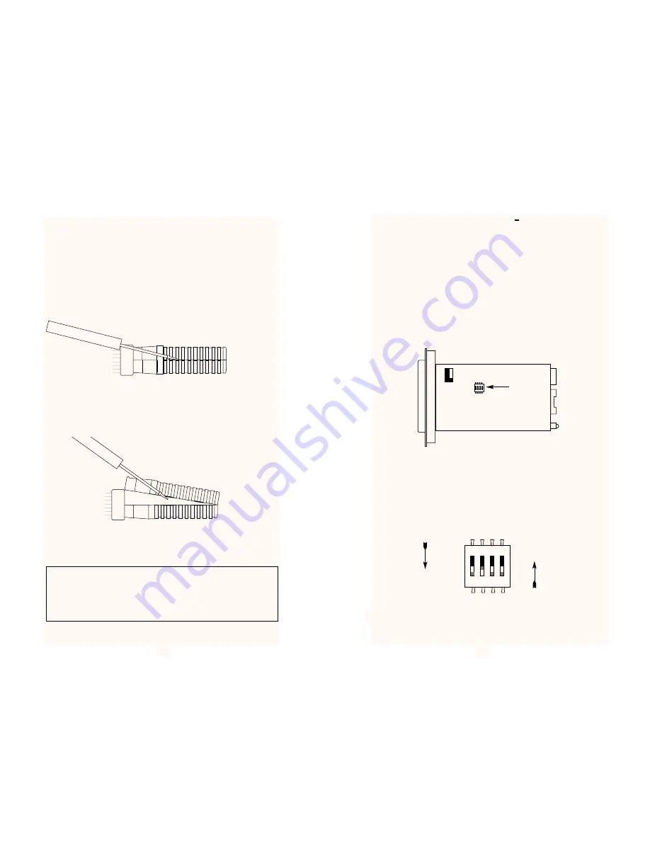
3.2.1  Configuration Switch Set “S1”

The four switches on DIP Switch S1 are used to select the test

mode and clock mode functions.  Figure 3 shows the position of Switch
S1 on the bottom side of the Model 2070/Ax PC board.

Figure 4 shows the orientation of the Switches on DIP Switch S1

with respect to ON/OFF positions.  The default settings for DIP switch
S1 are shown in the table on page 7.  Detailed descriptions of each
switch follow the table. 

6

Figure 4. Close-up of DIP Switches Showing “ON” and “OFF” Positions

ON

1

2

3

4

Figure 3. Location of Switch S1 on the bottom of the Model 2070/Ax PC board

ON

1 2 3 4

OFF

ON

Switch S1

1234

Summary of Contents for 2070 Series

Page 1: ...es V 24 X 21 V 35 to G 703 Interface Converter SALES OFFICE 301 975 1000 TECHNICAL SUPPORT 301 975 1007 http www patton com Part 07M2070 UM Doc 03106U2 001 Rev D Revised 10 25 06 C E R T I F I E D An...

Page 2: ...inability to use this product Patton Electronics specifically disclaims all other warranties expressed or implied and the installation or use of this product shall be deemed an acceptance of these te...

Page 3: ...stomer Service at 301 975 1007 2 1 FEATURES Bi directionally converts V 24 X 21 or V 35 to co directional G 703 Operates at 64 kbps synchronous data rate LED indicators monitor Test Mode and Synchroni...

Page 4: ...ircuits which may carry dangerous voltages Therefore the power and network cables must be disconnected prior to switch and jumper configuration 3 2 CONFIGURATION MODEL 2070 Ax V 24 VERSION The Model 2...

Page 5: ...ction Factory Default S1 1 Test Mode Off Disabled S1 2 Clock Mode On S1 3 Clock Mode On S1 4 Respond to LL Request On Disabled Network Clock 8 Switch S1 4 Response to DTE Request for Local Loopback Us...

Page 6: ...P1 Power Source 1 3 AC Powered JP2 SGND to FGND 5 6 Connected 3 3 CONFIGURATION MODEL 2070 Cx V 35 VERSION The Model 2070 Cx uses a mini DIP switch package and a jumper strap that allow configuration...

Page 7: ...11 MODEL 2070 Cx SWITCH S1 SUMMARY TABLE Position Function Factory Default S1 1 Test Mode Off Disabled S1 2 Clock Mode On S1 3 Clock Mode On S1 4 Response to LL Request On Disabled Network Clock Switc...

Page 8: ...efault JP1 Power Source 1 3 AC Powered JP2 SGND to FGND 5 6 Connected 3 4 CONFIGURATION MODEL 2070 Dx X 21 VERSION The Model 2070 Dx uses a mini DIP switch package and a jumper strap that allow config...

Page 9: ...fault S1 1 Test Mode Off Disabled S1 2 Clock Mode On Network S1 3 Byte Timing On Enabled S1 4 Reserved Off Switch S1 3 Byte Timing Use Switch S1 3 to enable byte timing on the Model 2040 Dx The Byte t...

Page 10: ...P2 JP1 4 0 INSTALLATION The Model 2070 is designed for 4 wire full duplex communication over a co directional 64 kbps G 703 clear channel network or dedicated twisted pair This section describes the p...

Page 11: ...n com or http www patton com for specific interface pin assignments 4 4 POWER CONNECTION The 120VAC U S wall transformer version supplies 5V regulated DC up to 300mA The variable 110 230VAC internatio...

Page 12: ...following page 21 TM SYNC Power Jack RJ45 Jack Figure 15 Model 2070 back panel LED indicators 22 G 703 Loop The G 703 Loop test allows the G 703 service provider to test the condition of the twisted...

Page 13: ...o 95 noncondensing Dimensions Model 2070 Ax 2 9 x 1 4 x 0 7 7 4 x 3 6 x 1 8 cm Model 2070 Cx 3 9 x 1 4 x 7 10 0 x 3 6 x 1 8 cm Model 2070 Dx 2 6 x 1 4 x 0 7 6 7 x 3 6 x 1 8 cm 23 APPENDIX B PATTON MOD...

Page 14: ...tzerland Power Cord 07M2070 User Manual 25 APPENDIX D PATTON MODEL 2070 INTERFACE PIN ASSIGNMENTS G 703 INTERFACE The G 703 Interface is an RJ 45 modular jack Pin Signal 1 RX Line Receive Positive 2 R...

Page 15: ...INDICATION A 6 SIGNAL TIMING A 7 8 SIGNAL GROUND TRANSMIT B 9 CONTROL B 10 RECEIVE B 11 INDICATION B 12 14 15 SIGNAL TIMING 12 1 Frame Ground 2 Transmit A 3 Control A 4 Receive A 5 Indication A 6 Sign...

Page 16: ......

Reviews: