background image

b)  This menu is displayed when the data format is asynchronous:

2. Data Format

Select Option 2 in the SOFTWARE CONFIGURATION Menu to

select the async or sync data format (See below).  This option controls
whether the unit operates in asynchronous or asynchronous data
formats.

3. Clock Mode

Select Option 3 in the SOFTWARE CONFIGURATION Menu to

select the sync clock mode (See below).

Set this option as follows:

Master Clock - Internal

:  Selection 1 allows the Model 

1092RC to generate an internal clock as the timing source.

Master Clock - External

:  Selection 2 allows the Model 

1092RC to Derive the system clock from the locally connected
DTE.

Slaved to Receive Clock:

Selection 3 to allows the Model 

1092RC to derive the timing source  from the incoming data 
stream from the remote Model 1092RC.

14

SGND & FRGND (JB4)

In the connected position, this strap links DB-25 pin 7 (Signal

Ground) and frame ground.  In the open position, pin 1 is disconnected
from frame ground. 

JB4

Position 1&2  =  SGND (Pin 7) and FRGND Connected
Position 2&3  =  SGND (Pin 7) and FRGND Not Connected

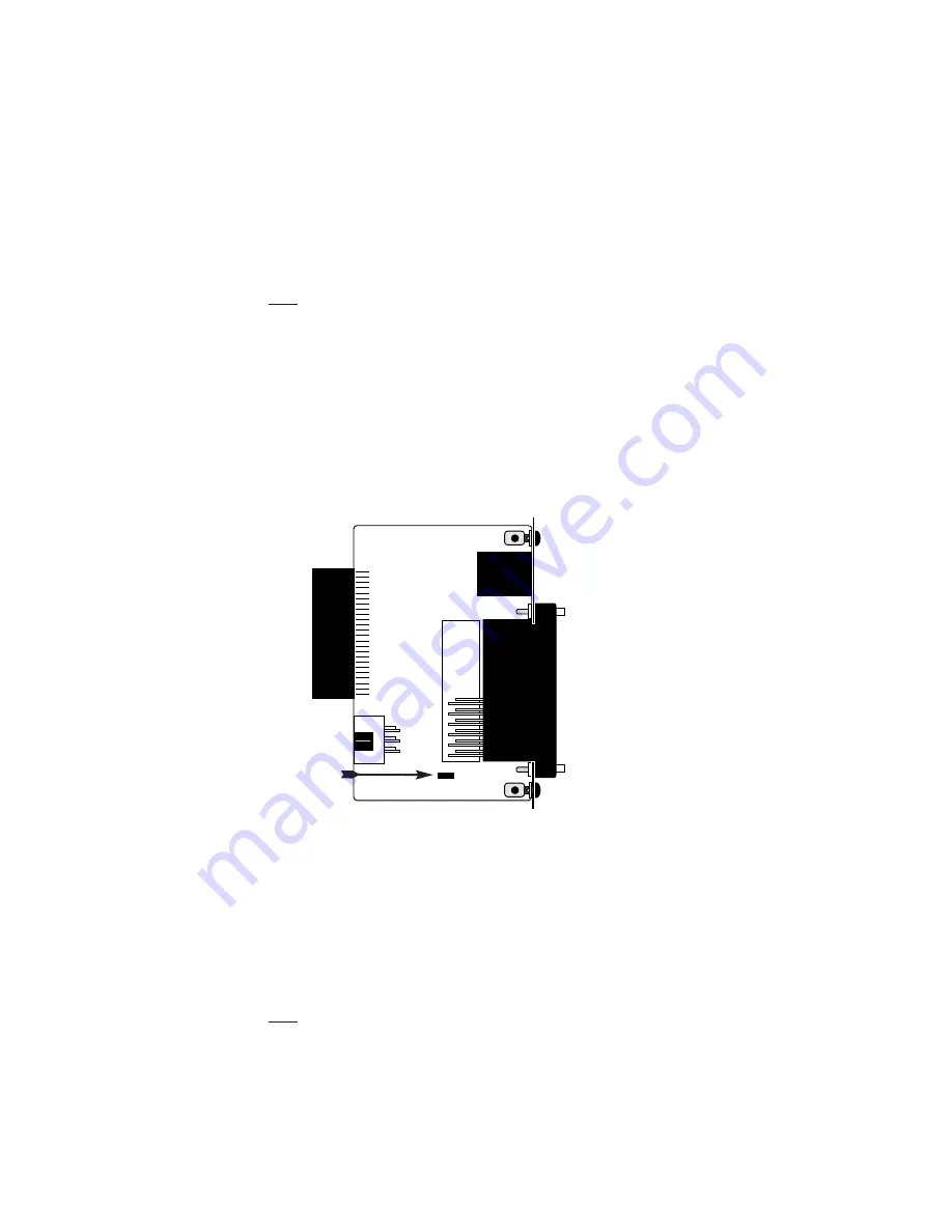
3.3.2  Model 1000RCM13492 Strap Settings

Figure 7 shows the strap location for the Model 1000RCM13492

(M/34/RJ-45) rear card.  This strap determines whether Signal Ground
and Frame Ground will be connected.  

SGND & FRGND (JB4)

In the connected position, this strap links Signal Ground and frame

ground. In the open position, signal ground is disconnected from frame
ground.

JB4

Position 1&2  =  SGND and FRGND Connected
Position 2&3  =  SGND and FRGND Not Connected

23

Figure 7.

M/34/RJ-45 strap locations

JB4

123

Summary of Contents for 1092RC

Page 1: ...2 Wire Synchronous and Asynchronous Rack Mount Modem Card SALES OFFICE 301 975 1000 TECHNICAL SUPPORT 301 975 1007 http www patton com Part 07M1092RC E Doc 033021U Rev F Revised 1 22 08 C E R T I F I...

Page 2: ...ings 3 3 2 Model 1000RCM13492 Strap Settings 4 0 Installation 24 4 1 The Model 1000R16P Rack Chassis 4 1 1 The Rack Power Supply 4 2 Installing the Model 1092RC Series Into Chassis 4 3 1 Connecting to...

Page 3: ......

Page 4: ...r This number may be obtained from Patton Electronics Technical Support tel 301 975 1007 email support patton com www http www patton com NOTE Packages received without an RMA number will not be accep...

Page 5: ......

Page 6: ...r board strap and two eight position DIP switches on the front card see Figure 1 below Figure 2 shows the orientation of the DIP switches with respect to the ON and OFF positions 5 ON 1 2 3 4 5 6 7 8...

Page 7: ......

Page 8: ...te On On 32 Kbps Reserved Off On 56 Kbps Reserved On Off 64 Kbps Reserved Off Off 19 2 or 128 Kbps 0 38 4 kbps NOTE Model 1092RC operates either at a synchronous rate of 19 2 kbps or 128 kbps dependin...

Page 9: ......

Page 10: ...see Appendix B In order to configure the Model 1092RC by software commands you must set its control port address The control port address is defined by a two digit decimal number Switches S2 1 throug...

Page 11: ......

Page 12: ...n Appendix D Refer to Appendix C to order a pre made cable 2 Power up the terminal and set its RS 232 port as follows 9600 Baud 8 data bits i stop bit no parity Local echo CR CR LF on inbound data ANS...

Page 13: ......

Page 14: ...nfiguration Select Option 4 toedit the software configuration of the Model 1092RC To save changes after editing the software configuration select MAIN MENU Option 5 then select Use Software Switches a...

Page 15: ......

Page 16: ...odel 1092RC to either respond or ignore the Remote Digital Loop request from the remote 1092RC 6 DTE Controlled Local Line Loop Select Option 6 in the SOFTWARE CONFIGURATION Menu to instruct the Model...

Page 17: ......

Page 18: ...ption 7 Test Modes Select Option 7 from the MAIN MENU to select the test mode status of the Model 1092RC below The Model 1092RC Test Mode settings help to verify the integrity of the data link and iso...

Page 19: ......

Page 20: ...ious parameters in the remote Model 1092RC 19 REMOTE UNIT CONFIGURATION MAIN MENU 1 Display Remote Unit Configuration 2 Setup Remote Unit Configuration 3 Display Remote Modem Status 4 Select Hardware...

Page 21: ......

Page 22: ...function cards Prior to installation you will need to examine the rear card you have selected and make sure it is properly configured for your application Each rear card is configured by setting strap...

Page 23: ......

Page 24: ...RCM13492 Strap Settings Figure 7 shows the strap location for the Model 1000RCM13492 M 34 RJ 45 rear card This strap determines whether Signal Ground and Frame Ground will be connected SGND FRGND JB4...

Page 25: ......

Page 26: ...the rack chassis and plug into each other by way of mating 50 pin card edge connectors Use the following steps as a guideline for installing each Model 1092RC Series into the rack chassis 1 Slide the...

Page 27: ......

Page 28: ...N SIGNAL TIP 4 4 TIP RING 5 5 RING 4 3 5 Connection to the Control Port Interface Please refer to the Model 1000CC Control Card user manual for cable requirements of the Control Port Interface 27 Noti...

Page 29: ......

Page 30: ...ese tests can be activated physically from the front panel or via the interface 5 2 1 Using Local Line Loopback LLB The Local Line Loopback LLB test checks the operation of the local Model 1092RC and...

Page 31: ......

Page 32: ...sent move the V 52 toggle switch to the right activating the 511 E test with errors present If the test is working properly the local modem s red ER LED will glow A successful 511 E test will confirm...

Page 33: ......

Page 34: ...1000RPSM 48A 48V Front Power Supply Module 1000RPEM V 120 240V CE Compliant Rear Power Entry Module 1000RPEM V 120 240V CE Compliant Rear Power Supply Entry Module 1000CC Control Card IM1RC A Interfac...

Page 35: ......

Page 36: ...Signal 1 FG Frame Ground 2 TD Transmit Data 3 RD Receive Data 4 RTS Request to Send 5 CTS Clear to Send 6 DSR Data Transfer Rate 7 SGND Signal Ground 15 TC Test Control A 17 RC Receive Timing 18 LLB L...

Page 37: ......

Page 38: ...NMENT RJ45 Connector Pin Number Signal 1 N C No Connection 2 N C No Connection 3 N C No Connection 4 Tip 5 Ring 6 N C No Connection 7 N C No Connection 8 N C No Connection Copyright 1997 Patton Electr...

Page 39: ......

Page 40: ......

Reviews: