


3.1.2 Configuration DIP Switch Set “S1”
The configuration switches on S1 allow you to specify the data
rate, async/sync data format, transmit clock source and response to
RDL request. Default settings of S1 are shown in the table below.
Switches S1-1 and S1-2: Data Rate
Use Switches S1-1and S1-2 to configure the data rate of the Model
1092RC. Each setting represents one synchronous data rate and one
asynchronous data rate.
S1-1
S1-2
Sync Data Rate
Async Data Rate
On
On
32 Kbps
Reserved
Off
On
56 Kbps
Reserved
On
Off
64 Kbps
Reserved
Off
Off
19.2 or 128 Kbps*
0 - 38.4 kbps
*NOTE:
Model 1092RC operates either at a synchronous rate of
19.2 kbps
or
128 kbps depending on the orientation of Switch S2.
To operate synchronously at 19.2 kbps, set Switch S2-1 ON. To
operate at 128 kbps, set Switch S2-1 OFF. See Section 3.1.3 for
more information.
7
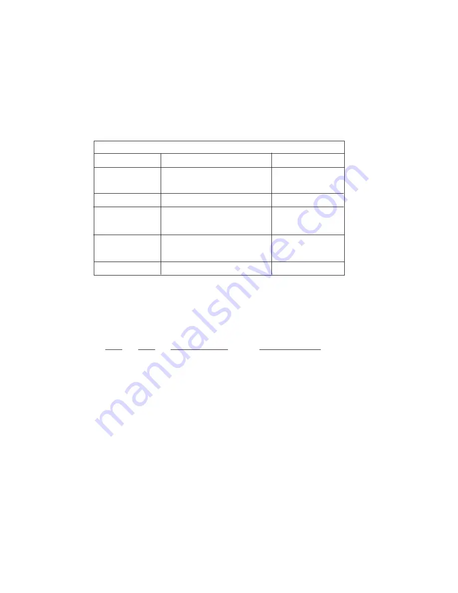
Position
Function
Factory Default
S1-1
Data Rate
On
S1-2
Data Rate
Off
S1-3
DSR during Local Line Loop
On
S1-4
Async/Sync Data Format
Off
S1-5
Async/Sync Data Format
Off
S1-6
Tx Clock Source
On
S1-7
Tx Clock Source
On
S1 SUMMARY TABLE
64K Sync
}
}
Async/Sync
Internal Clock
}
DSR Enable
NOTE
: Switch S1-8 must be in the “ON” position).
2.
Verify that the data terminal equipment is operating properly
and can be used for a test.
3. Perform a V.52 BER (bit error rate) test as described in
Section 5.2.3
. If the BER test equipment indicates no faults,
but the data terminal indicates a fault, follow the
manufacturer’s checkout procedures for the data terminal.
Also, check the interface cable between the terminal and the
Model 1092RC.
5.2.2 Using Remote Digital Loopback (RDL)
The Remote Digital Loopback (RDL) test checks the performance
of both the local and remote Model 1092RCs, and the communication
link between them. Any characters sent to the remote Model 1092RC
in this test mode will be returned back to the originating device (see
Figure 12, below). For example, characters typed on the keyboard of
the local terminal will appear on the local terminal screen after having
been passed to the remote Model 1092RC and looped back.
To perform an RDL test, follow these steps:
1.
Activate RDL. This may be done in two ways: first, by moving
the front panel toggle switch to the Left to “Remote”. Second,
by raising the RDL signal on the interface (see Appendix C).
NOTE:
Switch S1-8 must be in the “ON” position.
2.
Perform a V.52 BER test as described in
Section 5.2.3
. If the
BER test equipment indicates a fault, and the Local Line
Loopback test was successful for both Model 1092RCs, you
may have a problem with the twisted pair line between the
modems. You should then check the twisted pair line for
proper connections and continuity.
30
Figure 12.
Remote Digital Loop
Local 1092RC
Remote 1092RC
Summary of Contents for 1092RC
Page 3: ......
Page 5: ......
Page 7: ......
Page 9: ......
Page 11: ......
Page 13: ......
Page 15: ......
Page 17: ......
Page 19: ......
Page 21: ......
Page 23: ......
Page 25: ......
Page 27: ......
Page 29: ......
Page 31: ......
Page 33: ......
Page 35: ......
Page 37: ......
Page 39: ......
Page 40: ......


