- 31 -
PATON
ProTIG
DC TIG/MMA
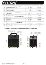
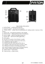
Control bodies of the machine
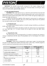
1
–
button
“Mode” –
switching welding mode;
2
–
button
“Program” –
selection of user program;
3
–
button
“Enter” –
saving the set up parameters of welding mode in memory of the
device;
4
–
button
“Up” –
changing the parameter value (higher);
5
–
button
“Down” –
changing the parameter value (lower);
6
–
button
“Right” –
selection of welding parameter;
7
–
button
“Left” –
selection of welding parameter;
8
–
LCD-screen;
9
–
Socket for connection of torch button or pedal;
10
–
Fitting for connection of gas hose on the torch;
11
–
Coolant flow relay connector;
12
–
Button/automatic switching on/off the device;
13
–
Cable for connection of the device to electric mains;
14
–
Fitting for connection of shielding gas cylinder;
15
–
Socket for power of autonomous cooling unit (400 V);
16
–
Location of the grounding cable connection;
А
–
Power socket
, “+” (red colour)
;
B
–
Power socket
, «
-
» (
black colour).
Summary of Contents for ProTIG-200
Page 1: ......
Page 2: ......
Page 8: ...7 PATON ProTIG DC TIG MMA 1 2 3 4 5 6 7 LCD 1 Mode TIG AC TIG DC...
Page 12: ...11 PATON ProTIG DC TIG MMA F 20 200 2 TIG C 2T TIG 2 2...
Page 13: ...PATON ProTIG DC TIG MMA 12 4 TIG C 4T 4 2 TIG 2T pulse...
Page 15: ...PATON ProTIG DC TIG MMA 14 zk zk F 2 TIG DC 2T TIG 2 2...
Page 16: ...15 PATON ProTIG DC TIG MMA 4 TIG DC 4T 4 2 TIG D 2T pulse...
Page 25: ...PATON ProTIG DC TIG MMA 24...
Page 26: ...25 PATON ProTIG DC TIG MMA 13 ProTIG 200 AC DC 2 ProTIG 315 400V AC DC 1 PATON...
Page 27: ...PATON ProTIG DC TIG MMA 26...


