


52
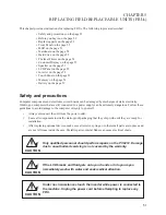
C H A P T E R 5 R E P L A C I N G F I E L D R E P L A C E A B L E U N I T S ( F R U s )
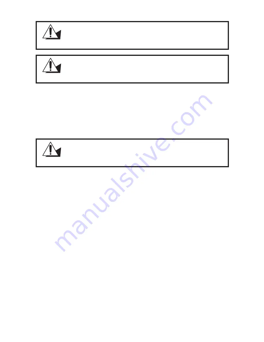
CAUTION
To prevent static damage to components, wear a grounded wrist strap.
Alternatively, discharge any static electricity by touching the bare metal
chassis of the unit case, or the bare metal body of any other grounded
appliance.
CAUTION
Hold electronic circuit boards by the edges only. Do not touch the
components on the board unless it is necessary to do so. Do not flex or
stress the circuit board. Do not hold components such as a processor
by its pins; hold it by the edges.
CAUTION
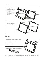
To prevent scratching the case of the PT-6212, make sure the worktop
surface is clean and flat. If you need to put the display facing down, be
sure to use a foam mat.
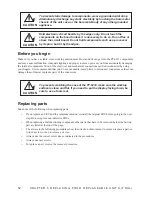
Before you begin
Make sure you have a stable, clean working environment. Dust and dirt can get into the PT-6212 components
and may cause malfunction. Adequate lighting and proper tools can prevent you from accidentally damaging
the internal components. Most of the electrical and mechanical connections can be disconnected by using
your fingers. It is recommended that you do not use needle-nosed pliers to disconnect connectors as these can
damage the soft metal or plastic parts of the connectors.
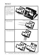
Replacing parts
Take note of the following when replacing parts:
If you replace an FRU and the symptom remains, reinstall the original FRU before going to the next
•
step. Do not replace non-defective FRUs.
When replacing a malfunctioning component, other parts that have to be removed before the failing
•
part are listed at the top of the page.
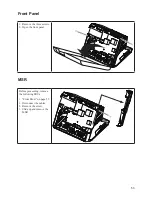
The arrows in the following procedures show the direction of movement to remove/replace a part, or
•
to turn a screw or key to release a device.
Always use the correct screw size as indicated in the procedures.
•
Always use new screws.
•
To replace a part, reverse the removal procedure.
•
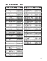
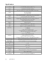
Summary of Contents for PT-6212
Page 1: ...All in one POS Terminal PT 6212 Service Manual...
Page 2: ......
Page 8: ...vi...
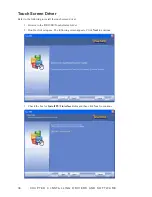
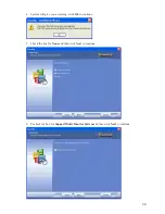
Page 43: ...35 Click 5 Next to continue Click 6 Next to continue...
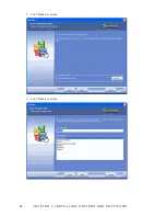
Page 45: ...37 Click 3 Install to begin installation When installation is completed click 4 Finish...
Page 68: ...60 C H A P T E R 5 R E P L A C I N G F I E L D R E P L A C E A B L E U N I T S F R U s...
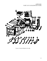
Page 69: ...61 APPENDIX PART LIST AND SPECIFICATION Exploded diagram main parts Figure 6 1...
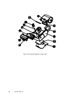
Page 70: ...62 A P P E N D I X Exploded diagram printer parts Figure 6 2...


