


16
C H A P T E R 2 B I O S S E T U P
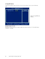
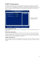
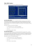
Integrated Peripherals
This option defines the operation of peripheral components on the system’s input/output ports.
Onboard Serial Port 3/4/5/6
These items allow you to select an address for the third and fourth serial ports. The default setting is
3E8/2E8/4F8/4E8.
Serial Port 3/4/5/6 Use IRQ
These items allow you to select an corresponding interrupt for the third and fourth serial ports. The default
setting is IRQ5/IRQ10/IRQ11/IRQ5.
Com1/2 With Voltage
COM1/2 port can be set to supply both data and power to the peripherals that connect to them. Check if the
device you connect needs power from the COM1/2 port or if it has its own power supply. The factory setting
is None.
IMPORTANT
The voltage for the COM ports is set at None at the factory. However,
for example to provide power to an installed customer display, this
setting must be set at 12V for the corresponding COM port. For a 5V
device such as a barcode scanner, the setting should be 5V.
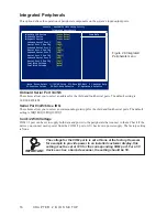
Integrated
Figure 2.8
Peripherals menu
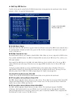
Phoenix - AwardBIOS CMOS Setup Utility
Integrated Peripherals
OnChip IDE Device
►
[Press Enter]
Onboard Device
►
[Press Enter]
SuperIO Device
►
[Press Enter]
Onboard Serial Port 3
[3E8]
Serial Port 3 Use IRQ
[IRQ5]
Onboard Serial Port 4
[2E8]
Serial Port 4 Use IRQ
[IRQ10]
Onboard Serial Port 5
[4F8]
Serial Port 5 Use IRQ
[IRQ11]
Onboard Serial Port 6
[4E8]
Serial Port 6 Use IRQ
[IRQ5]
Com1 With Voltage
[None]
Com2 With Voltage
[None]
Item Help
↑↓→←:Move Enter:Select +/-/PU/PD:Value F10:Save ESC:Exit F1:General Help
F5:Previous Values F6:Fail-Safe Defaults F7:Optimized Defaults
Summary of Contents for PT-6212
Page 1: ...All in one POS Terminal PT 6212 Service Manual...
Page 2: ......
Page 8: ...vi...
Page 43: ...35 Click 5 Next to continue Click 6 Next to continue...
Page 45: ...37 Click 3 Install to begin installation When installation is completed click 4 Finish...
Page 68: ...60 C H A P T E R 5 R E P L A C I N G F I E L D R E P L A C E A B L E U N I T S F R U s...
Page 69: ...61 APPENDIX PART LIST AND SPECIFICATION Exploded diagram main parts Figure 6 1...
Page 70: ...62 A P P E N D I X Exploded diagram printer parts Figure 6 2...


