background image

Integrated Peripherals 


33

ON: Set on to USB emulation. (Default value)

USB Keyboard Support 

Enable this item if you plan to use a keyboard connected through the USB port in a legacy operating system (such as 
DOS) that does not support Plug and Play. The default setting is Enabled.

Press <Esc> to return to the Integrated Peripherals menu.
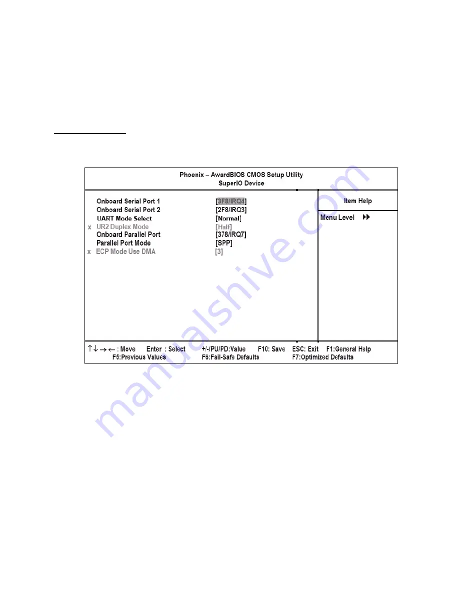
SuperIO Device

Use this item to change settings for I/O devices. Select the item and press <Enter> to open the following menu:

Figure 3.11

Super I/O Device menu

Onboard Serial Port 1 

This option is used to assign the I/O address and IRQ for the onboard serial port 1 (COM1). The default setting is 3F8/
IRQ4.

Onboard Serial Port 2 

This option is used to assign the I/O address and IRQ for the onboard serial port 2 (COM2). The default setting is 2F8/
IRQ3.

UART Mode Select

This item allows you to determine which ItDA function of Onboard I/O chip.

Normal:  Disable IrDA function.

IrDA: Enable IrDA Function.

ASKIR: Enable ASKIR mode, with 56Kbps transfer rate.

SCR: CRE in synchronous slave mode only

Summary of Contents for PT-5700

Page 1: ...PT 5700 User manual...

Page 2: ......

Page 3: ...t generates uses and can radiate radio frequency energy and if not installed and used in accordance with the instructions may cause harmful interference to radio communications However there is no gua...

Page 4: ...utlet Do not place anything on the power cord Place the power cord where it will not be in the way of foot traffic Follow all warnings and cautions in this manual and on the unit case When replacing p...

Page 5: ...USB ports can be damaged if care is not taken when connecting devices Ensure USB devices are correctly inserted Plugging a phone line into the LAN port RJ 45 connector can damage the con nector Take...

Page 6: ...iv...

Page 7: ...ns 13 Before you begin 14 Installing a hard disk drive HDD 14 Installing a CompactFlash card 15 Chapter 3 BIOS Setup Utility 17 About the Setup Utility 17 Entering the Setup Utility 18 BIOS navigation...

Page 8: ...nd User Passwords Options 43 Save Exit Setup Option 43 Exit Without Saving 43 Appendix 45 Troubleshooting 45 Tips for Troubleshooting 45 The Power On Self Test 45 Beep Errors at POST 45 Beep Message E...

Page 9: ...3 3 IDE Primary Master Submenu 20 Figure 3 4 Advanced Chipset Features menu 23 Figure 3 5 DRAM Clock Drive Control menu 24 Figure 3 6 AGP P2P Bridge Control menu 27 Figure 3 7 CPU PCI Bus Control menu...

Page 10: ...viii...

Page 11: ...ay on page 7 Adjusting display angles on page 8 Setup considerations on page 9 Connecting peripheral devices on page 9 Connecting a cash drawer on page 10 Powering the PT 5700 on and off on page 10 Un...

Page 12: ...the following items are included If any item is missing or appears damaged contact your dealer immediately PT 5700 SOME UNITS SHIP WITH CUSTOMER DISPLAY AND MSR INSTALLED POWER CABLE AND ADAPTER CD RO...

Page 13: ...nnectors on the PT 5700 Front right view Figure 1 2 Front right view of PT 5700 DESCRIPTION 1 15 inch TFT LCD touch screen 2 Power LED 3 Power button USB cover NOTE There are two USB connectors under...

Page 14: ...4 Chapter 1 Getting Started Rear right view Figure 1 3 Rear right view of PT 5700 DESCRIPTION 1 Customer display cover 2 Magnetic card reader cover 3 Rear cover 4 Rear cover latches 4 3 2 1...

Page 15: ...cted DESCRIPTION 1 RJ 45 connector 2 PS 2 mouse connector 3 COM 3 connector 4 Parallel connector 5 COM 2 connector 6 Act LED green lights when network activity is detected 7 Link LED orange lights whe...

Page 16: ...to remove the rear cover CAUTION Plugging a phone line into the LAN port RJ 45 connector can damage the con nector Take care to only plug an RJ 45 connector into the LAN port 1 Rotate the display unti...

Page 17: ...er to the following to attach it 1 Remove the rear cover See Removing the rear cover on page 6 2 Remove the screw 3 Push with your thumbs as shown and lift up to remove the panel cover 4 While pushing...

Page 18: ...s as shown in Figure 1 5 The customer display can be tilted as shown in Figure 1 6 6 Connect the customer display cable 7 Align the grooves on the customer display bracket and slide the customer displ...

Page 19: ...as a printer or scanner can be connected to the PT 5700 Refer to the user manual of the device you are connecting for instructions on installing drivers where needed Remove the rear cover to access t...

Page 20: ...ash drawer 3 Turn on the PT 5700 See Powering the PT 5700 on and off below Powering the PT 5700 on and off Refer to the following to power on and off the PT 5700 IMPORTANT The cash drawer RJ 11 connec...

Page 21: ...wer LED A turns on 5 To turn off the PT 5700 shut down the operating system the main power turns off automatically NOTE You may need to use the main power button to turn off the power for example if t...

Page 22: ...12 Chapter 1 Getting Started...

Page 23: ...flakes can cause electrical shorts CAUTION Only qualified personnel should perform repairs on the PT 5700 Damage due to unauthorized servicing is not covered by the warranty If you are not confident o...

Page 24: ...s these can damage the soft metal or plastic parts of the connectors Installing a hard disk drive HDD Refer to the following to install a HDD CAUTION To prevent scratching the case of the PT 5700 make...

Page 25: ...ng a Compact Flash card replace the cover to prevent the card being accidently removed while power is on Refer to the following to install a CompactFlash card 1 Remove the screw and the card reader co...

Page 26: ...16 Chapter 2 Upgrading Components...

Page 27: ...P PCI Configurations on page 38 PC Health Status on page 40 Frequency Voltage Control on page 41 Other BIOS Options on page 42 About the Setup Utility The BIOS Setup Utility enables you to configure t...

Page 28: ...e Award BIOS Setup Utility Figure 3 1 Main BIOS menu BIOS navigation keys The BIOS navigation keys are listed below KEY FUNCTION Scrolls through the items on a menu PU PD Modifies the selected field s...

Page 29: ...a triangle lead to submenus that enable you to change the values for the option Use the cursor arrow keys to scroll through the items in the submenu Standard CMOS features Selecting Standard CMOS Fea...

Page 30: ...s that are in the same location on every disk surface Head displays the number of heads in the HDD A head is a device that reads and writes data on the hard disk Precomp displays the track where preco...

Page 31: ...Power On Self Test routine You can use this item to select which types of errors in the POST are sufficient to halt the system Base Memory Extended Memory and Total Memory These items are automatical...

Page 32: ...l 1 L1 and level 2 L2 cache memory to improve performance Leave this item at the default setting for better performance The default setting is Enabled CPU L2 Cache ECC Checking This item enables or di...

Page 33: ...O S 1 4 OS Select For DRAM 64 MB This item is only required if you have installed more than 64 MB of memory and you are running the OS 2 operating system Otherwise leave this item at the default The...

Page 34: ...ave these items at the default value The default setting is Enabled Video RAM Cacheable These items allow the video RAM to be cached in memory for faster execution We recommend that you leave these it...

Page 35: ...ng refreshed The default is Disabled Precharge to Active Trp This item is used to designate the minimum Row Precharge time of the SDRAM devices on the module DRAM must continually be refreshed or it w...

Page 36: ...26 Chapter 3 BIOS Setup Utility RDSAIT selection Set RDSAIT to 03 Default value 03 Press Esc to return to the Advanced Chipset Features menu...

Page 37: ...um that you can assign to VGA is 64 MB The default setting is 16 MB Select Display Device If you connect an external display to the PT 5700 you can use this setting to turn off LCD and only use the ex...

Page 38: ...t compliance with PCI specification version 2 1 The default setting is Enabled VLink mode selection This menu item controls the data transfer speed between the north and south bridge By Auto VLink mod...

Page 39: ...t MSR setting Onboard Serial Port 3 This option is used to assign the I O address for the onboard serial port 3 COM3 which is used for the rear customer display The default setting is 3E8 Serial Port...

Page 40: ...e default setting for COM4 is None Onboard Serial Port 5 This option is used to assign the I O address for the onboard serial port 5 COM5 The default setting is 4F8 Serial Port 5 Use IRQ This option i...

Page 41: ...t Default value Disabled Disable onboard 1st channel IDE port OnChip IDE Channel1 Enabled Enable onboard 2nd channel IDE port Default value Disabled Disable onboard 2nd channel IDE port IDE Prefetch M...

Page 42: ...s Enabled Press Esc to return to the Integrated Peripherals menu VIA OnChip PCI Device Use this item to enable or disable the PCI devices that are integrated on the mainboard Select the item and press...

Page 43: ...item and press Enter to open the following menu Figure 3 11 Super I O Device menu Onboard Serial Port 1 This option is used to assign the I O address and IRQ for the onboard serial port 1 COM1 The de...

Page 44: ...owing both data input and output ECP and EPP modes are only supported with EPP and ECP aware peripherals PntMode allows the parallel port to operate in bipoloar mode ECP Mode Use DMA When the onboard...

Page 45: ...if the video is powered down when the system is put into suspend mode The default setting is Sus pend Off Video Off Method This item defines how the video is powered down to save power The default set...

Page 46: ...ystem from the power saving mode to an active state Disabled Disabled this function Default value Ctrl F1 Ctrl F12 Set PS 2 keyboard wakeup from S4 S5 to Ctrl F1 Ctrl F12 Power Press power key to wake...

Page 47: ...the system from a suspended state to an active state Disabled Disable this function Default value Enabled Enable modem ring resume RTC Alarm Resume When set to Enabled the following two fields become...

Page 48: ...I Configurations This option configures how PnP Plug and Play and PCI expansion cards operate in the system Both the ISA and PCI buses on the mainboard use system IRQs Interrupt ReQuests and DMAs Dire...

Page 49: ...lem by changing this item to Manual and then opening up the IRQ Resources sub menu IRQ Resources This menu can only be accessed when the Resources Controlled by menu is set to Manual In the IRQ Resour...

Page 50: ...tatus On mainboards that support hardware monitoring this item lets you monitor the parameters for critical voltages and critical temperatures These fields are display only Figure 3 16 PC Health Statu...

Page 51: ...the CPU clock runs relative to the bus speed Auto Detect DIMM PCI Clk When enabled BIOS disables the clock signal of unpopulated PCI slots reducing power consumption The default set ting is Enabled S...

Page 52: ...he system working properly again If you only want to load fail safe defaults for a specific option select and display that option and then press F6 Load Optimized Defaults Option This option opens a d...

Page 53: ...prompted to confirm the password 5 Type the password again and press Enter or press Enter if you are deleting a password that is already installed Write the passwords down and keep them in a safe pla...

Page 54: ...44 Chapter 3 BIOS Setup Utility...

Page 55: ...ical support or for passing on to service personnel Use some other electrical device to confirm that the electrical outlet is working Ensure all connections are securely attached The Power On Self Tes...

Page 56: ...eset floppy subsystem Have the PT 5700 serviced FLOPPY DISK S FAIL 40 Floppy type mismatch Have the PT 5700 serviced HARD DISK S FAIL 80 HDD reset failed Have the PT 5700 serviced HARD DISK S FAIL 40...

Page 57: ...e the PT 5700 serviced An unidentified message is displayed Reboot the computer and run the BIOS Setup Utility Con firm the Setup Utility parameters If the same message is displayed after booting up a...

Page 58: ...he infrared port Make sure of the following The IR function is enabled The infrared ports are clean No objects are between the computer and the communicat ing device Incorrect data is sent by IR betwe...

Page 59: ...48 pin BGA CN700 Northbridge support 100 MHz FSB SB VIA 487 pin BGA VT8237R Plus Southbridge BIOS Award Plug and Play BIOS Supports APM and ACPI 4M bits flash ROM Support boot on LAN Jumper free setti...

Page 60: ...OM2 supports rear customer display when the customer dis play is on there is no COM2 port available One DB 25 for LPT Port One 6 pin D SUB for PS 2 KB connector auto routing for MSR 2 USB ports on fro...

Reviews: