192-011006N8 PSD1 Installation Guide
192-011006N8 2019-07
09.10.19 09:27
31 (109)
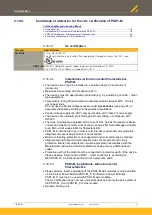
4.3.3.
View from above (PSD1-S)
Front view (see page 29)
X60 (see page
PC interface to configure and program servo axes
X61 (see page
Fieldbus Interface output
X62 (see page
Fieldbus Interface input
X63 (see page
Terminals
•
AC Mains Supply
•
DC power supply
•
Connection of braking resistor
or
bridge
to activate the internal braking resistor
View from below (see page 30)
Shows pin 1 of the connector
4.4
P14: Status LED (PSD1-S)
Status
No.
Status of axis
Left LED a
(green) (ready)
Right LED b
(red) (error)
0
No voltage
off
off
1
Booting of axis, firmware is
missing
alternate quick flashing
(LEDa green, LEDb rot)
2
Axis not ready:
•
Booting of axis
•
No feedback detected.
•
IEC61131-3 program not
compatible with firmware.
•
no IEC61131-3 program
•
Hall signals invalid.
off
flashes quickly (5 HZ)
3
Axis de-energized
flashes slowly
off
4
Axis energized; commutation
calibration running
flashes quickly
off
5
Axis energized
on
off
6
Axis in error state / error
present / axis energized (error
reaction 1)
on
flashes quickly (5 HZ)
7
Axis in error state / error
present / axis de-energized
(error reaction 2)
off
on
8
Axis faulty: Please contact us
on
on
9
STO active
off
flashes slowly (1 HZ)
10
reserved
flashes quickly
flashes quickly (5 HZ)
11
SD Card detected or
restoring from SD card
successfully terminated
alternate quick flashing
(LEDa green, LEDb green)
12
SD card not detected or
restoring from SD card
interrupted
alternate quick flashing
(LEDa red, LEDb red)
13
Axis de-energized
off
Single flash


