192-011006N8 PSD1 Installation Guide
192-011006N8 2019-07
09.10.19 09:27
29 (109)
4.3
Connector overview PSD1-S
In this chapter you can read about:
•
Front view (PSD1-S) ................................................................................................................. 29
•
View from below (PSD1-S) ....................................................................................................... 30
•
View from above (PSD1-S) ....................................................................................................... 30
4.3.1.
Front view (PSD1-S)
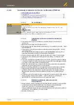
CAUTION: Risk of electric shock
Caution - Risk of electric shock!
Before wiring or loosening electrical connections please observe the
following:
•
Risk of electric shock, disconnect power before removing cover resp.
disconnect the devices from the mains supply.
•
Caution!
Dangerous electrical voltage even after turning off the intermediate
capacitors:
Up to
3 minutes with PSD1-S and 10 minutes with PSD1-M
after switching off
mains supply, dangerous voltages may still be present.
Please check that no voltages are present (<50 V) at the output terminals DC+
and DC- of PSD1-S: X63/3 & X63/5 and with PSD1-M: Bus HV DC - 3 & 5. rail.
View from above (see page 30)
P10
Status LEDs for the fieldbus
C11
Slot for SD card
(SD card not included in delivery)
S12 (see page
Device address higher value half-byte (accept with
power ON)
S13 (see page
Device address low value half-byte (accept with
power ON)
P14 (see page
Status LED device
X17 (see page
Digital inputs/outputs
X18 *
Feedback device Male Connector (Resolver (see
page 101), Encoder/Hall (see page 37))
S33
For safety option
S34
For safety option
View from below (see page 30)
*
Before connecting a feedback cable, check that the correct feedback system is
configured in the device.
Otherwise, destruction of the feedback system is threatened by overvoltage!


