192-011006N8 PSD1 Installation Guide
192-011006N8 2019-07
09.10.19 09:27
61 (109)
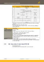
Acceptance of the switch position when switching on 24 VDC Control voltage
Operation with switch positions 9 ... F can destroy the device
* Switch positions 7 and 8 are intended solely for commissioning!
Continuous mode in this switch position is not allowed.
5.12.5.
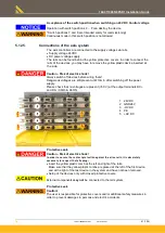
Connections of the axis system
The axis controllers are connected to the supply voltages via rails.
•
Supply voltage 24VDC
•
DC power voltage supply
The rails can be found behind the yellow protective covers. In order to connect the
rails of the devices, you may have to remove the yellow plastic device inserted at
the side.
Caution - Risk of electric shock!
Always switch off devices before wiring them!
Dangerous voltages are still present until 10min. after switching off the power
supply.
Please check that no voltages are present (<50 V) at the output terminals DC+
and DC- (X63/3 & X63/5).
1 24VDC
2 GND24V
3 -HV DC
4 PE
5 +HV DC
Protective seals
Caution - Risk of electric shock!
In order to secure the contact protection against the alive rails, it is absolutely
necessary to respect the following:
•
Insert the yellow plastic comb at the left and right of the rails.
Make sure that the yellow plastic combs are placed at the left of the first device
and at the right of the last device in the system and have not been removed.
•
Setup of the devices only with closed protective covers.
External components
may not
be connected to the rail system.
Protective seals
Caution!
The user is responsible for protective covers and/or additional safety measures in
order to prevent damages to persons and electric accidents.


