Parker Hiross Hyperchill ICE360 User Manual Download Page 17

   English

7/8

   ICE310-360

5 Maintenance

a) Th

  e machine is designed and built to guarantee continuous opera-

tion; however, the life of its components depends on the mainte-
nance performed.  

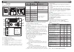
b) When requesting assistance or spare parts, identify the machine 

(model and serial number) by reading the dataplate located on the 
unit. 

c) Circuits containing 3 kg or more of refrigerant fl uid are checked to 

identify leaks at least once a year.
Circuits containing 30 kg or more of refrigerant fl uid are checked to 
identify leaks at least once every six months. ((EU) No. 517/2014 art. 
4.3.a, 4.3.b).

d) For machines containing 3 kg or more of refrigerant fl uid, the op-

erator must keep a record stating the quantity and type of refrigerant 
used, an quantities added and that recovered during maintenance 
operations, repairs and fi nal disposal ((EU) No. 517/2014 art. 6). An 
example of this record sheet can be downloaded from the site: www.
polewr.com.

5.1 General instructions

Before performing any maintenance, make sure the power to the 

refrigerator is disconnected.

Y

 Always use the Manufacturer’s original spare parts: otherwise the 

Manufacturer is relieved of all liability regarding machine malfunction-
ing.

Y

 In case of refrigerant leakage, contact qualifi ed and authorized 

personnel.

Y

 Th

  e Schrader valve must only be used in case of machine malfunc-

tion: otherwise any damage caused by incorrect refrigerant charging 
will not be covered by the warranty.

5.2 Preventive maintenance

To guarantee lasting maximum chiller effi

  ciency and reliability, carry 

out:

a) 

every 4 months -

 clean the condenser fi ns and make sure com-

pressor electrical absorption is within the dataplate values;

b) 

Z


yearly - W

 version: in case of encrustations inside the con-

denser, introduce and circulate a specifi c detergent liquid.

b) 

Every 3 years - 

installation of kit for maintenance every 3 

years. (par.7.7) 

a) 

kit for maintenance every 3 years;

b)

service kit;

1. compressor 

kit;

2. fan 

kit;

3. 

P3 pump kit;

4. 

expansion valve kit

c) 

individual spare parts.

5.3 Refrigerant

Charging: any damage caused by incorrect charging carried out by 

unauthorized personnel will not be covered by the warranty.

Y

 Th

  e equipment contains fl uorinated greenhouse gases.

At normal temperature and pressure, the R407C refrigerant is a col-
ourless gas classifi ed in SAFETY GROUP A1 - EN378 (group 2 fl uid 
according to Directive PED 97/23/EC);
GWP (Global Warming Potential) = 1774.

In case of refrigerant leakage, air the room.
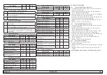
5.4 Dismantling

Th

  e refrigerant and the lubricating oil contained in the circuit must be 

recovered in conformity with current local environmental regulations.
Th

  e refrigerant fl uid is recovered before fi nal scrapping of the equip-

ment ((EU) No. 517/2014 art.8).

%

Recycling

Disposal

frame and panels

steel/epoxy resin polyester

tank

aluminium/copper/steel

pipes/collectors

copper/aluminium/carbon steel

pipe insulation

NBR rubber

compressor

steel/copper/aluminium/oil

condensator

steel/copper/aluminium

pump

steel/cast iron/brass

fan

aluminium

refrigerant

R407C (HFC)

valve

brass/copper

electrical cable

copper/PVC

Summary of Contents for Hyperchill ICE360

Page 1: ...Hyperchill 50Hz ICE310 ICE360 DATE 25 02 2016 Rev 20 CODE 398H271677 IT Manuale d uso EN User Manual ES Manual de uso DE Benutzer Handbuch...

Page 2: ......

Page 3: ...ONE Il costruttore si riserva il diritto di modificare le informazioni contenute nel presente manuale senza alcun preavviso Ai fini di una completa ed aggiornata informazione si raccomanda all utente...

Page 4: ...la pompa con sistemi anti colpo d ariete Controlli preliminari 1 Controllare che le eventuali valvole di intercettazione del circuito idraulico siano aperte 2 Se il circuito idraulico di tipo chiuso c...

Page 5: ...sul pannello posteriore della macchina e collegare fase e neutro ai morsetti del sezionatore generale QS la terra va collegata all apposito morsetto di terra PE 3 Assicurare all origine del cavo di a...

Page 6: ...icare il corretto funzionamento della pompa utilizzando il manometro leggere P1 e P0 e i valori limite di pressione Pmax e Pmin riportati sulla targa dati della pompa P1 pressione con pompa ON P0 pres...

Page 7: ...aore compressore 3 H3 D Contaore compressore 2 H2 D Contaore compressore 4 H4 D Soglia allarme contaore compressore 1 tHI U 0 Soglia allarme contaore compressore 3 tH3 U 0 Soglia allarme contaore comp...

Page 8: ...Allarme protezione compressore 2 Fasi invertite M ID12 P14 L9 Allarme protezione compressore 4 Fasi invertite M ID13 1 AC2 Allarme a disposizione circuito 2 M 4 6 2 Allarmi da ingressi analogici AI CO...

Page 9: ...garanzia 5 2 Manutenzione preventiva Per garantire nel tempo la massima efficienza ed affidabilit del chiller eseguire a Z ogni 4 mesi pulizia alette condensatore e verifica assorbi mento elettrico c...

Page 10: ...TUIRE IL FILTRO ALETTE DEL CONDENSATORE SPORCHE PULIRE LE ALETTE DEL CONDENSATORE SUPERFICIE DEL CONDENSATORE OSTRUITA LIBERARE LA SUPERFICIE FRONTALE DEL CONDENSATORE PORTATA ACQUA INSUFFICIENTE AUME...

Page 11: ...ANT The manufacturer reserves the right to modify this manual at any time For the most comprehensive and updated information the user is advised to consult the manual supplied with the unit 1 4 Residu...

Page 12: ...and outlet pipelines Y If the hydraulic circuit is intercepted by automatic valves protect the pump with an anti hammering system Preliminary checks 1 Check that any shut off valves in the water circ...

Page 13: ...m cable section see par 7 5 2 Pass the cable through the cable entry on the rear panel of the ma chine and connect the phase and neutral to the terminals of the main isolator switch QS connect the ear...

Page 14: ...pump using the pressure gauge read P1 and P0 and checking the pressure limit values Pmax and Pmin indicated on the pump data plate P1 pressure with pump ON P0 pressure with pump OFF Pmin P1 P0 Pmax E...

Page 15: ...U 0 Compressor 1 operation hour counter HI D Compressor 3 operation hour counter H3 D Compressor 2 operation hour counter H2 D Compressor 4 operation hour counter H4 D Compressor 1 hour counter thres...

Page 16: ...rm compressor 2 Phases monitor M ID12 PI4 L9 Protection alarm compressor 4 Phases monitor M ID13 1AC2 Circuit 2 alarm available M 4 6 2 Allarmi da ingressi analogici AI CODE DESCRIPTION RESET B1 HAI T...

Page 17: ...ranty 5 2 Preventive maintenance To guarantee lasting maximum chiller efficiency and reliability carry out a Z every 4 months clean the condenser fins and make sure com pressor electrical absorption i...

Page 18: ...FILTER CLOGGED RENEW THE FILTER CONDENSER FINS DIRTY CLEAN THE FINS OF THE CONDENSER CONDENSER SURFACES CLOGGED CLEAR THE FRONT SURFACE OF THE CON DENSER INSUFFICIENT WATER FLOW INCREASE THE FLOW RATE...

Page 19: ...s componentes ATENCI N El fabricante se reserva el derecho de modificar sin previo aviso la informaci n de este manual Para que la informaci n resulte completa se recomienda al usuario consultar el ma...

Page 20: ...os de entrada y salida del agua Y Si el circuito hidr ulico posee v lvulas autom ticas de corte proteger la bomba con sistemas contra golpe de ariete Controles preliminares 1 Cerciorarse de que las v...

Page 21: ...n m nima del cable vea el apartado 7 5 2 Pasar el cable por el sujetacables situado en el panel posterior del equipo conectar la fase y el neutro a los bornes del seccionador general QS y la tierra al...

Page 22: ...ar el funcionamiento correcto de la bomba utilizando el man metro leer P1 y P0 y los valores l mite de presi n Pm x y Pm n indicados en la placa de datos de la bomba P1 presi n con bomba ON P0 presi n...

Page 23: ...mpresor 2 AbC2 U 0 Habilitaci n compresor 4 AbC4 U 0 Cuentahoras del compresor 1 HI D Cuentahoras del compresor 3 H3 D Cuentahoras del compresor 2 H2 D Cuentahoras del compresor 4 H4 D L mite de alarm...

Page 24: ...larma protecci n del compresor 2 Fases invertidas M ID12 P14 L9 Alarma protecci n del compresor 4 Fases invertidas M ID13 1AC2 Alarma disponible circuito 2 M 4 6 2 Allarmi da ingressi analogici AI C D...

Page 25: ...trario los da os causados por una carga incorrecta de refrigerante no ser n reconocidos en garant a 5 2 Mantenimiento preventivo Para garantizar la m xima eficacia y fiabilidad del refrigerador hay qu...

Page 26: ...TASCADO SUSTITUIR EL FILTRO ALETAS DEL CONDENSADOR SUCIAS LIMPIAR LAS ALETAS DEL CONDENSADOR SUPERFICIE DEL CONDENSADOR OBSTRUIDA LIBERAR LA SUPERFICIE FRONTAL DEL CONDENSADOR CAUDAL DE AGUA INSUFICIE...

Page 27: ...zifikationen und oder deren Bauteile und oder Optionen f r die korrekte bzw in vern nftiger Weise vorhersehbare Nutzung der Anlage bzw der Bauteile ausreichen ACHTUNG Der Hersteller beh lt sich das Re...

Page 28: ...bfilter installiert werden Y Wird der Wasserkreis durch automatisch ansprechende Ventile gesperrt ist die Pumpe durch geeignete Wasserschlag Schutzsysteme zu sch tzen Vorabkontrollen 1 Kontrollieren o...

Page 29: ...s tze wird mit einem 4 Leiter Kabel 3 Pole Erde ohne Neutralleiter hergestellt Bez glich des Kabel Mindestquerschnitts siehe Abschnitt 7 5 2 Das Kabel durch die Kabelschelle am r ckseitigen Paneel der...

Page 30: ...Den korrekten Betrieb der Pumpe mit einem Druckmesser P1 und P0 ablesen und die Druckgrenzwerte Pmax e Pmin auf dem Typenschild der Pumpe berpr fen P1 Druck Pumpe ON P0 Druck Pumpe OFF Pmin P1 P0 Pma...

Page 31: ...4 AbC4 U 0 Betriebsstundenz hler Verdichter 1 HI D Betriebsstundenz hler Verdichter 3 H3 D Betriebsstundenz hler Verdichter 2 H2 D Betriebsstundenz hler Verdichter 4 H4 D Alarmschwelle Betriebsstunden...

Page 32: ...orrichtung Verdichter 2 falsche Drehrichtung M ID12 P14 L9 Alarm Schutzvorrichtung Verdichter 4 falsche Drehrichtung M ID13 1AC2 Alarm zur Verf gung Kreis 2 M 4 6 2 Alarme von den Analogeing ngen AI C...

Page 33: ...Einheit einzusetzen anderenfalls werden Sch den infolge unkorrekter K ltemittelbef llung nicht von der Garan tie abgedeckt 5 2 Vorbeugende Wartung F r eine stets optimale Effizienz und Zuverl ssigkeit...

Page 34: ...ERSETZEN RIPPEN DES KONDENSATORS VERSCHMUTZT RIPPEN DES KONDENSATORS REINIGEN OBERFL CHE DES KONDENSATORS BEDECKT BEDECKUNG AN FRONTOBERFL CHE DES KONDENSATORS ENTFERNEN WASSER VOLU MENSTROM UN ZUREIC...

Page 35: ......

Page 36: ...Corsico MI Italy Sede Operativa Hiross Zander Filtration Division Strada Zona Industriale 4 35020 S Angelo di Piove PD Italy tel 39 049 971 2111 fax 39 049 9701911 Web site www parker com hzd e mail t...

Reviews: