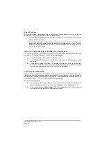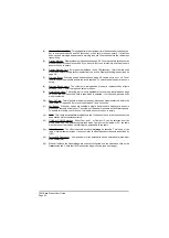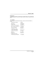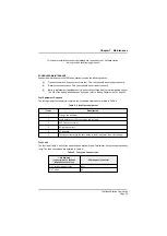
Table 10. Battery Replacement
Battery Usage
Replacement After
Not used. Battery kept fully charged.
8 years.
Battery used until fully discharged (that is, 2 hours use
at 10% duty cycle).
60 discharges.
Battery used for approximately 1 hour at 10% duty
cycle (50% discharge).
120 partial discharges.
Battery used for approximately 30 minutes at 10% duty
cycle (25% discharge).
240 partial discharges.
Battery used for approximately 10 minutes at 10% duty
cycle (10% discharge).
600 partial discharges.
FAULT FINDING
Warning!
Neither the Power button, nor the rear panel Power switch, isolates the input supply from the
equipment. Lethal voltages are still present in the base station's internal power supply. To
ensure safe working during maintenance, the ac and dc input supplies must be
disconnected from the base station.
The T6M base station contains the following replaceable modules (see Figures 6, 7, and 8):
q
A T6M radio module (a self-contained transceiver).
q
An interface module that interconnects the various external signals, and the power supplies, to
the radio module.
q
A switched mode power supply (SMPS).
The base station's modules are manufactured using surface mount technology. Because of this, and the
specialist test equipment required to set up the circuits, spares are limited to modules and components
as listed on page 47.
The following table gives help in fault diagnosis.
T6M Base Station User Guide
Page 53
Summary of Contents for T6M
Page 1: ...T6M Base Station User Guide Handbook Part Number 31 360T6MBS...
Page 12: ...Intentionally Blank T6M Base Station User Guide Page 12...
Page 16: ...Intentionally Blank T6M Base Station User Guide Page 16...
Page 48: ...Intentionally Blank T6M Base Station User Guide Page 48...
Page 56: ...Intentionally Blank T6M Base Station User Guide Page 56...
Page 58: ...Intentionally Blank T6M Base Station User Guide Page 58...
Page 59: ...BT6MBS 01 Front and Rear Layout Figure 1...
Page 60: ...BT6MBS 13 Rack Mounted Version Figure 2...
Page 62: ...BT6MBS 11 External Connection Diagram Figure 4...
Page 63: ...BT6MBS 10 Enclosure Securing Detail Figure 5...
Page 64: ...Base Station Block Diagram Figure 6 GA10547 Iss 3...
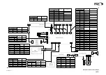
Page 65: ...Base Station Interconnection Diagram Figure 7 GA10548 Iss 3...
Page 66: ...Base Station Layout Diagram Figure 8 GA10719 Iss 1...
Page 69: ...Interface PCB Layout Diagram Figure 11 GA10751 Iss 1...
Page 70: ...BT6MBS 12 1 Cable Termination at the N Type Connector Figure 12...


