


Chapter 4: Infrared Object Detection · Page 39
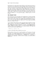
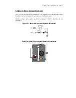
Figure 4.4: SumoBot IR Object Detection Components Installed
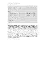
TESTING THE IR PAIRS
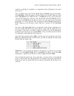
The key to making each IR pair work is to send one millisecond of unfiltered 38.5 kHz
FREQOUT
harmonic followed immediately by testing the signal sent by the IR detector
and saving its output value. The IR detector’s normal output state when it sees no IR
signal is high (logic 1). When the IR detector sees the 38.5 kHz harmonic sent by the IR
LED, its output will drop from high to low (logic 0). Of course, if the IR does not reflect
off an object, the IR detector’s output simply stays high. Program 4.1 shows an example
of this method of reading the detectors
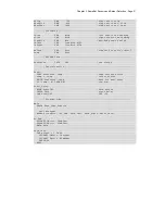
' SumoBot_4.1_IR_Sensor_Test.BS2
' {$STAMP BS2}
' {$PBASIC 2.5}
' -----[ I/O Definitions ]-------------------------------------------------
LfIrOut PIN 4 ' left IR LED output
LfIrIn PIN 11 ' left IR sensor input
RtIrOut PIN 15 ' right IR LED output
RtIrIn PIN 14 ' right IR sensor input
Summary of Contents for Boe-Bot
Page 1: ...SumoBot Mini Sumo Robotics Assembly Documentation and Programming VERSION 2 1...
Page 4: ......
Page 9: ...Preface Page ix...
Page 10: ......
Page 20: ......
Page 32: ......
Page 54: ......
Page 74: ......
Page 76: ......
Page 77: ...Appendix D SumoBot PCB Schematic Page 67 Appendix D SumoBot PCB Schematic...


