


Page 30 · SumoBot – Mini Sumo Robotics
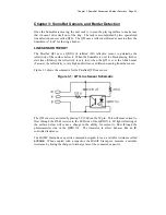
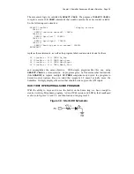
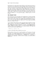
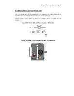
Figure 3.4: Start LED Connections on the SumoBot PCB
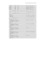
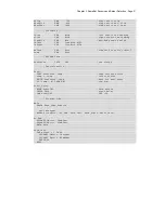
' SumoBot_3.3_Simple_Mini_Sumo.BS2
' {$STAMP BS2}
' {$PBASIC 2.5}
' -----[ I/O Definitions ]-------------------------------------------------
LMotor PIN 13 ' left servo motor
RMotor PIN 12 ' right servo motor
LLinePwr PIN 10 ' left line sensor power
LLineIn PIN 9 ' left line sensor input
RLinePwr PIN 7 ' right line sensor power
RLineIn PIN 8 ' right line sensor input
StartLED PIN 0 ' display start delay
' -----[ Constants ]-------------------------------------------------------
LFwdFast CON 1000 ' left motor fwd; fast
LFwdSlow CON 800 ' left motor fwd; slow
LStop CON 750 ' left motor stop
LRevSlow CON 700 ' left motor rev; slow
LRevFast CON 500 ' left motor rev; fast
RFwdFast CON 500 ' right motor fwd; fast
RFwdSlow CON 700 ' right motor fwd; slow
Summary of Contents for Boe-Bot
Page 1: ...SumoBot Mini Sumo Robotics Assembly Documentation and Programming VERSION 2 1...
Page 4: ......
Page 9: ...Preface Page ix...
Page 10: ......
Page 20: ......
Page 32: ......
Page 54: ......
Page 74: ......
Page 76: ......
Page 77: ...Appendix D SumoBot PCB Schematic Page 67 Appendix D SumoBot PCB Schematic...


