


Chapter 3: SumoBot Sensors and Border Detection · Page 27
lbLeft VAR lineBits.BIT1
lbRight VAR lineBits.BIT0
' -----[ Program Code ]----------------------------------------------------
Main:
GOSUB Read_Line_Sensors
DEBUG HOME, "LR", CR, ' show sensor readings
BIN2 lineBits, CR, CR
SELECT lineBits ' display actions
CASE %00
DEBUG "Continue forward", CLREOL
CASE %01
DEBUG "Spin Left", CLREOL
CASE %10
DEBUG "Spin Right", CLREOL
CASE %11
DEBUG "Back up and turn around", CLREOL
ENDSELECT
GOTO Main
END
' -----[ Subroutines ]-----------------------------------------------------
Read_Line_Sensors:
HIGH LLinePwr ' activate sensors
HIGH RLinePwr
HIGH LLineIn ' discharge caps
HIGH RLineIn
PAUSE 1
RCTIME LLineIn, 1, lLine ' read left sensor
RCTIME RLineIn, 1, rLine ' read right sensor
LOW LLinePwr ' deactivate sensors
LOW RLinePwr
' convert readings to bits
LOOKDOWN lLine, >=[1000, 0], lbLeft ' 0 = black, 1 = line
LOOKDOWN rLine, >=[1000, 0], lbRight
RETURN
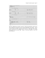
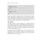
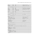
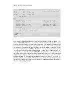
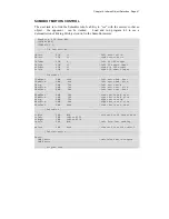
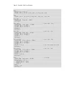
HOW IT WORKS
This program takes the working QTI code and incorporates into a unified subroutine.
The end of the subroutine converts the analog values from the QTI sensors to a single
nibble value that contains the status of both sensors. Incorporating both sensor readings
into a single variable streamlines the SumoBot robot's border avoidance logic.
Summary of Contents for Boe-Bot
Page 1: ...SumoBot Mini Sumo Robotics Assembly Documentation and Programming VERSION 2 1...
Page 4: ......
Page 9: ...Preface Page ix...
Page 10: ......
Page 20: ......
Page 32: ......
Page 54: ......
Page 74: ......
Page 76: ......
Page 77: ...Appendix D SumoBot PCB Schematic Page 67 Appendix D SumoBot PCB Schematic...


