


Chapter 2: SumoBot Locomotion · Page 13
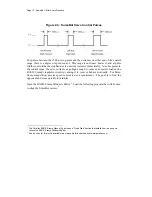
programmed to produce this waveform using any of its I/O pins. In this example, the
BASIC Stamp sends a 1500
µ
s pulse to P13 (left servo) and P12 (right servo). When the
pulse is done being executed the signal pin is low. Then, the BASIC Stamp creates a 20
ms pause.
Figure 2.3: Servo Pulse Train Analysis
This pulse train has a 1500
µ
s high time and a 20 ms low time. The high time is the main
ingredient for controlling a servo’s motion, and it is most commonly referred to as the
pulse width. Since these pulses go from low to high (0V to 5V) for a certain amount of
time, they are called positive pulses. Negative pulses would involve a resting state that’s
high with pulses that drop low.
The ideal pause between servo pulses is 20 milliseconds, but can be anything between 10
and 40 milliseconds without adversely affecting the servo’s performance.
The BASIC Stamp 2’s
PULSOUT
instruction works in increments of 2 micro-
seconds. For example, the following snippet of code creates a 1500
µ
s pulse:
PULSOUT P13, 750 ' 1500 us pulse on pin 13
A pulse width of 1500
µ
s (normally, the centering command) will cause the modified
servo to stop. To make the servo turn we must give change the pulse width toward either
end of the standard control range of 1000 to 2000
µ
s. Since the right side servo motor is
physically mirrored from the left, its control signals are as well. Figure 2.3 shows the
control signaling for the SumoBot servos.
Summary of Contents for Boe-Bot
Page 1: ...SumoBot Mini Sumo Robotics Assembly Documentation and Programming VERSION 2 1...
Page 4: ......
Page 9: ...Preface Page ix...
Page 10: ......
Page 20: ......
Page 32: ......
Page 54: ......
Page 74: ......
Page 76: ......
Page 77: ...Appendix D SumoBot PCB Schematic Page 67 Appendix D SumoBot PCB Schematic...


