background image

Page 8 of 28

Part No. 100318  Rev. 1

Issued: 2021-06-08

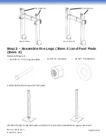
2-A) Assemble the 4 legs and 4 foot pads:

2-B) Bolt the legs to the foot pads using the 9/16” wrenches (remember to apply anti-seize):

Step 2 - Assemble the Legs (Item 3) and Foot Pads 

(Item 4)

Hardware Required:
•  4x 3/8”-16 - 3.75” Long Hex Bolts


•  4x 3/8”-16 - Kep Nuts


•  8x 3/8” - Flat Washers

P/N 100430 x4

P/N 100431 x4

Rear H-Frame

Front H-Frame

Summary of Contents for PH-6K-5

Page 1: ... 6K 5 PH 6K 6 PH 8K 4 PH 8K 5 Part No 100318 Rev 1 Issued 2021 06 08 Paradise Dock Lift Inc 4311A 25 Ave Vernon BC Canada V1T 1P5 paradisedocklift com info paradisedocklift com 1 888 411 3625 PH 8K 5 SHOWN COPYRIGHT 2021 PARADISE DOCK LIFT INC READ CAREFULLY PRIOR TO INSTALLATION AND USE RETAIN THIS DOCUMENTATION ...

Page 2: ...d patented retracted when up configuration ensures the maximum cylinder life by preventing rod pitting corrosion and increasing seal life Our hydraulic fluid is non toxic and biodegradable so you do not need to worry about environmental harm We hope you enjoy your Paradise Hydraulic Boatlift Model Factory Specifications PH 6K 5 PH 6K 6 PH 8K 4 PH 8K 5 Rated Capacity 6000 lbs 2722 kg 6000 lbs 2722 ...

Page 3: ...g a load All persons must stay clear of lift while the lift is in operation Never service a boatlift boat or boatlift accessory while the lift is supporting a load Your lift system is not intended to support people never actuate the lift with people on board Unload and load passengers only when the boat is floating and not supported by the lift Never exceed the lift s rated capacity The gross load...

Page 4: ...rrect and inadequate support may result in boat damage Paradise Dock Lift can not determine guarantee warrant or take responsibility for bunk support configurations meeting each manufacturers recommendation CAUTION During the first few operations of the lift the weight of the watercraft may cause the lift to settle Stay well away from the lift during actuation until it is seen that the installatio...

Page 5: ... 2 100341 100051 6 Cross Beam 2 100088 7 Hydraulic Cylinder 2 100003 8 Bunk 2 100086 9 Bunk Rubber 2 100087 10 Guide On optional 4 100102 11 Extension Arm 4 100070 100325 100430 100431 100070 12 Cylinder Kit includes hoses and fittings not shown 1 13 Pump not shown 1 14 Power Pack includes box and pump not shown 1 COMPONENT OVERVIEW 2 Cylinder Hydraulic Boatlift Models 10 1 2 11 3 5 9 8 7 4 6 Dire...

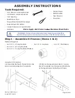
Page 6: ... to warranty issues hazards or the lift misfunctioning Step 1 Assemble H Frames Items 1 2 Hardware Required 8x 1 2 13 4 Long Hex Bolts 8x 1 2 13 4 5 Long Hex Bolts 8x 1 2 13 5 Long Hex Bolts PH 8K 4 16x 1 2 13 Kep Nuts 32x 1 2 Flat Washers Note Apply Anti Seize to ALL Stainless Steel Bolts Marine Grease Rubber mallet Tape Measure Pencil Pen Using the 3 4 wrenches 1 A Assemble the Rear H Frame Bolt...

Page 7: ...Complete one side of an H Frame Rear H Frame shown 1 D Repeat steps A B for the other side Rear H Frame shown 1 E Repeat Steps A D for the Front H Frame assembly Use the bottom set of bolt holes on the leg extensions item 11 in order to raise the top of the leg extensions by 2 5 This ensures a raised pitch of the bunks Top bolt hole on leg extension is exposed on the Front H Frame Leg Extension It...

Page 8: ... pads 2 B Bolt the legs to the foot pads using the 9 16 wrenches remember to apply anti seize Step 2 Assemble the Legs Item 3 and Foot Pads Item 4 Hardware Required 4x 3 8 16 3 75 Long Hex Bolts 4x 3 8 16 Kep Nuts 8x 3 8 Flat Washers P N 100430 x4 P N 100431 x4 Rear H Frame Front H Frame ...

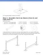
Page 9: ...6 Kep Nuts 8x 1 2 13 Kep Nuts 8x 3 8 Flat Washers 16x 1 2 Flat Washers 3 A Assemble the 2 cross beams on the 4 legs Set the height of the cross beams such that the top of the cross beams remain 24 inches below the water surface at the lowest water depth of the installation location See the Installation section of this manual for further details 2 C Torque the bolted connection to 23 ft lbs ...

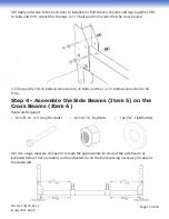
Page 10: ...16 4 5 Long Hex Bolts 8x 3 8 16 Kep Nuts 16x 3 8 Flat Washers 4 A Use a tape measure and pencil to mark the approximate location of the side beams as indicated below These locations can be adjusted to suit the bunk spacing necessary to support the watercraft 3 B Apply anti seize to the bolts prior to installation Bolt the cross beams and legs together 3 8 16 bolts and 9 16 wrench for the legs 1 2 ...

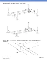
Page 11: ...age 11 of 28 Part No 100318 Rev 1 Issued 2021 06 08 4 B Assemble the Side Beams on to the 2 cross beams 4 C Use the 9 16 wrenches and hardware to loosely bolt and clamp the side beams to the cross beams ...

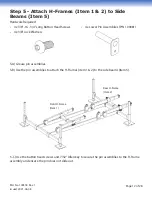
Page 12: ...d Screws 4x 3 8 Lock Washers 4x Lower Pin Assemblies P N 100081 5 A Grease pin assemblies 5 B Use the pin assemblies to attach the H Frames item 1 2 to the side beams item 5 5 C Use the button head screws and 7 32 Allen key to secure the pin assemblies to the H Frame assembly and ensure the pin does not slide out Front H Frame Item 1 Rear H Frame Item 2 ...

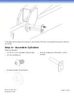
Page 13: ... Cylinders Hardware Required 4x 3 8 16 3 4 Long Button Head Screws 4x 3 8 Lock Washers 4x Pin Assemblies 2x P N 100077 2x P N 100180 8x Plastic Washers P N 100276 5 D Tighten the hardware from step 4 C now that the H Frames are attached Torque the 3 8 bolts to 23 ft lbs ...

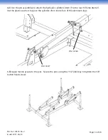
Page 14: ...ttach the hydraulic cylinders item 7 to the rear H Frame item 2 Use the plastic washers to space the cylinders from inside face of the aluminum lugs 6 B Apply marine grease to the pins Secure the pins using the 7 32 Allen key to tighten the 3 8 button head screws P N 100180 P N 100077 ...

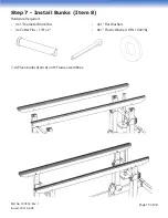
Page 15: ...No 100318 Rev 1 Issued 2021 06 08 Step 7 Install Bunks Item 8 Hardware Required 4x 1 Diameter Bunk Pins 4x Cotter Pins 1 8 x 2 4x 1 Flat Washers 8x 1 Plastic Washers P N 100276 7 A Place bunks item 8 on H Frame assemblies ...

Page 16: ...the inside surfaces of the bunk as spacers Use cotter pins and flat washer to secure bunk pins Bend the end of the cotter pin with the needle nose pliers to secure the pins Step 8 Install Guide Ons Item 10 Optional Hardware Required 8x 3 8 16 6 Long Hex Bolts 4x 3 8 16 4 Long Hex Bolts 12x 3 8 16 Kep Nuts 24x 3 8 Flat Washers ...

Page 17: ...ift into position WARNING Note the correct locations indicated above by the check marks incorrect installation can cause damage to the lift frame and or bunks X X X X 8 B Bolt guide ons to bunk using 3 8 16 x 6 long bolts Apply anti seize tighten the bolts with 9 16 wrench and torque to 23 ft lbs ...

Page 18: ...e and guide on covers over the guide on tube The guide ons are adjustable to different boat widths 9 A Mount plastic hose clips to the inside of side beams using 8 self tapping screws as shown in the image below A third clip is included in the hardware kit to facilitate hose routing and can be mounted to the dock or anywhere required Ziptie the hoses as shown and route the hoses under the side bea...

Page 19: ...nimum required for the hoses to not bind when the lift actuates Step 10 Connect Power Pack 10 A Connect quick connect hydraulic fittings to power pack Use a 3 4 wrench to hold the fitting and 1 1 4 wrench to tighten the quick connect Note If quick connects are difficult to connect relieve some pressure by pressing the male end on a hard surface Use eye protection when doing this and be cautious no...

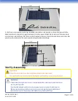
Page 20: ...Optional 11 A To install the solar panels to the power pack first locate the orientation of the solar panel on the lid of the power pack as shown below Mark the location of the solar panel black electrical connection on the lid of the power pack approx 3 inches from edge of lid and use a 7 8 drill bit to drill a 7 8 hole in the lid Insert the solar panel electrical wire into the power pack Secure ...

Page 21: ... and secure the solar panels using double sided tape Verify Assembly CAUTION Check that all bolts have been tightened and cotter pins bent Be careful when working around hydraulics and battery wear eye protection WARNING Check that the hydraulic hose is routed under the side beam and that there are no pinch points Test the lift initially with no load actuate it several cycles Verify that no fittin...

Page 22: ...ft height above the water should be maximized to reduce the chances of waves contacting your watercraft To launch your lift roll your lift if wheel kits are included or float your lift to the installation location The boatlift assembly with wheel kits installed is shown below To float install your lift 250 lb floatation bags should be attached to the front and rear H Frames of the lift A certified...

Page 23: ...ng legs prior to installing leg braces Secure the Lift Feet If your area sees high waves or a steep slope you may want to consider installation of rebar anchors not included to anchor the lift feet positions Hammer 4 pieces of 2 4 foot 1 2 inch diameter rebar through the holes in each of the feet if doing so Lift the Boat for the First Time Begin by positioning the boat with the transom 12 to 18 i...

Page 24: ...to battery maintenance If a replacement battery is needed a 12V group 31 marine battery is recommended The minimum recommended reserve capacity is 160 amp hours It is recommended that the battery capacity not drop below 50 capacity as a trickle or solar charge will have difficulty fully recharging The battery may require a trickle charge during the off season or a boost at the beginning and end of...

Page 25: ...isconnect the quick connect lines and bring the power pack box indoors Issue Diagnosis Issue Battery terminals hot Battery not staying charged Remote control not working Lift does not actuate with hard wired controller Hydraulic hoses are difficult to connect Hydraulic fluid in power pack box Lift is noisy squeaky when operating Potential Solution Check tightness of battery terminals ensure no cor...

Page 26: ...Upon receipt of a completed warranty request form and after confirmation by the company that the product is defective the company or it s authorized dealer or agent will at the company s discretion repair the product replace the defective part with a reconditioned or new part or refund the price of the product Reasonable proof of the defect must be provided by the purchaser to the company or compa...

Page 27: ...sed from company but used on non company products are excluded from this warranty Warranty is void if the product has been re purchased within the stated warranty period For boatlift applications intended for marine use sacrificial zinc anodes must be installed on the boatlift to mitigate galvanic corrosion of the structural components Limitations To the maximum extent permitted by law except as e...

Page 28: ...08 Page 28 of 28 Paradise Dock Lift Inc 4311A 25 Ave Vernon BC Canada V1T 1P5 paradisedocklift com info paradisedocklift com 1 888 411 3625 SPECIFICATIONS INSTRUCTIONS SUBJECT TO CHANGE WITHOUT NOTICE COPYRIGHT 2021 PARADISE DOCK LIFT INC ...

Reviews: