background image

PAR T GOLF DOUBLE EAGLE INSTALLATION AND MAINTENANCE MANUAL 


D10  

SECTION D     THE ELECTRONICS        

C

hapter 

8


T

HE

V

IDEO

 P

ROJECTOR 


R

ecommended procedures for installing and fine tuning the video projector are outlined in this chapter.  Refer 

to the projector manufacturer's maintenance manual for specific instruction on any adjustments. 


The projector is focused and tested by Par T Golf technicians prior to shipment.  Only fine tuning should be 
required when installing the projector on-site.  To learn more about the projector, refer to its installation and/or 
operation manual.


WARNING: Never connect or disconnect electronic cables while power is on to the control console.  
Doing so may seriously damage your equipment and void your warranty.  The projector lamp is not 
covered under warranty, by the manufacturer or by Optronics, Ltd..  Care should be taken to operate 
the projector according to manufacturer’s guidelines.  Failure to do so will result in premature failure of 
projector lamp. 


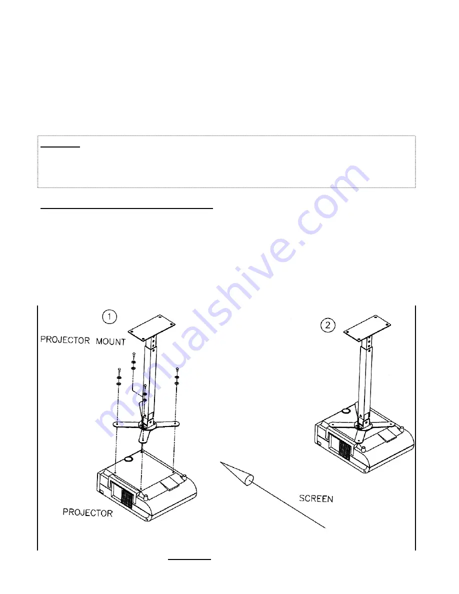
ATTACH PROJECTOR TO MOUNT


STEP 1


Attach the Projector to the 
Projector Mount 


  Drawing 8A


Lift the projector into place and secure with supplied hardware as 
shown in Drawing 8A.  Be extraordinarily careful as not to drop the 
projector when installing.  

Optronics bears no responsibility for 

damge to projector if dropped.


STEP 2


Ensure the projector is 
secure to the mount prior to 
releasing.


There is no warranty to protect you if the projector is dropped 
and/or damaged.


For your own safety and to protect the 

projector from damage, use extreme caution when installing the 
projector.


Drawing 8A    Projector Installation 


Summary of Contents for Double Eagle Elite Plus 4

Page 1: ...ATION AND MAINTENANCE MANUAL THE DOUBLE EAGLE ELITE PLUS 4 EAGLE STROKE GOLF OPTRONICS LTD 365 Bugatti Ave Salt Lake City Utah 84115 optronet gmail com www eaglestroke com 801 486 5407 Phone 801 486 6...

Page 2: ...creen Assembly C2 Section D THE ELECTRONICS Chapter 6 The Par T Optisense D3 Chapter 7 The Control Console D6 Chapter 8 The Video Projector D10 Section E ENJOYING YOUR MACHINE Chapter 9 Marking the Pu...

Page 3: ...n attractive framework These components compose of 1 The Platform Fashioned from wood and covered by decorative putting carpet it serves as the base for the entire system All construction and installa...

Page 4: ...nly if you need more information to complete that step Technical Support If you run into problems installing or using your new Double Eagle this manual is the best place to quickly find help Check Cha...

Page 5: ...ball flight tracking system It is housed in a topless metal enclosure measuring 16 x 6 x 48 406 x 152 x 1219 mm and includes three overhead cameras three infrared lights and accompanying fans Video P...

Page 6: ...ows for maximum enjoyment and worry free operation The maintenance and installation guide is an important factor in the operation of the Double Eagle It is comprised of important information about the...

Page 7: ...oot of space on left side of platform Optional One foot of space on the left side of the platform is recommended to expand the golfer s swinging area and for equipment servicing Allow one foot of spac...

Page 8: ...er is not stable If a dependable power source is not available a constant voltage harmonic neutralized transformer must be used to power the entire system Though not required where a stable source of...

Page 9: ......

Page 10: ...igures 1 6 B5 Platform Construction Drawings Chapter 4 Putting Carpet Installation B12 Placing the Tri Turf B13 KEY VOCABULARY Dedicated Circuit An electrical circuit complete with breaker used solely...

Page 11: ...4 1 1 2 X 3 1 2 51 x 102mm 38 x 89mm ITEM NO QTY LENGTH DESCRIPTION 1 1 168 4267 mm 2 4 65 1651 mm 3 2 68 1 2 1740 mm 4 6 161 4089 mm 5 4 79 3 4 2026 mm LAY ALL 2 x 4s FLAT ON THE FLOOR 6 4 96 2438 m...

Page 12: ...7 3226 mm from the screen end of the platform This will be directly above the overhead Optisense when installed STEP 8 Install box 3 for the video projector Electrical box 3 should be mounted in the...

Page 13: ......

Page 14: ......

Page 15: ......

Page 16: ......

Page 17: ......

Page 18: ......

Page 19: ...Place and unroll carpet Unroll the carpet beginning at the screen end of the putting platform Allow unrolled carpet one hour to relax The carpet should be allowed to lay unrolled and to relax for at...

Page 20: ...TRI TURF STEP 8 Set Tri Turf into place Figure 6 _ Locate the plywood pieces removed for the Tri Turf cut out and place them in the hole on the floor Set the Tri Turf into place on top of plywood scr...

Page 21: ...een to canopy and frame C8 Drawing 5F C8 Assembled Screen Assemble and install projector mount C9 Drawing 5G C9 Steel Projector Mount Expanded View KEY VOCABULARY Canopy The canopy is designed in one...

Page 22: ...lower platform Assemble Items 1 2 7 8 and 7 each 9 forming a base shaped like a U on the platform Drawing 5A Secure each joint with one of the self threading 5 16 bolts provided Be sure to put a bolt...

Page 23: ...PAR T GOLF DOUBLE EAGLE INSTALLATION AND MAINTENANCE MANUAL SECTION C THE FRAME C3 Drawing 5A Steel Modular Frame Expanded View...

Page 24: ...PAR T GOLF DOUBLE EAGLE INSTALLATION AND MAINTENANCE MANUAL C4 THE FRAME SECTION C Drawing 5B Putting Light Receptacle Installation...

Page 25: ...belts from Points C to G and B to F on each side Re adjust all straps to assure they are reasobably tight STEP 6 Attach screen to upper back of frame Lay the screen on the platform with dark flap bot...

Page 26: ...orresponding lower corners Secure each connection with the self threading 5 16 bolts provided STEP 9 Install Padding pipe insullation Wrap all the front straight pieces of the frame assembly points A...

Page 27: ...lengths of shock cord labeled SIDE Tie shock cord to the upper frame corner piece at Point F Using Method C unite one side of screen and one side of canopy by threading cord through wire clips and aro...

Page 28: ...astened to prevent projector movement STEP 14 Attach mount to ceiling and position projector _ Attach upper mount to ceiling using lag screws or toggle bolts Align mount in the center and above the re...

Page 29: ...ector in the Mount D10 Drawing 8A D10 Projector Installation Connecting Cable to the Projector D11 Drawing 8B D11 Projector Cable Connection Diagram KEY VOCABULARY Control Console The control center f...

Page 30: ...fine tuning the brightness and contrast usinb the remote control This process is specifically outlined in the projector s installation manual READ IT and refer to it for futher instruction VGA Cable...

Page 31: ...BLES WHILE POWER IS ON TO CONTROL CONSOLE DOING SO MAY SERIOUSLY DAMAGE YOUR EQUIPMENT AND VOID YOUR WARRANTY INSTALLING THE PAR T OPTISENSE STEP 1 Suspend Optisense from Frame Drawing 6A Suspend Opti...

Page 32: ......

Page 33: ...kwise 90 degrees Plug is keyed to fit one way Drawing 6B Point light toward tee to illuminate driving area during play IMPORTANT Focus light on the hitting surface so that it provides maximum light fo...

Page 34: ...n of the facility owner STEP 2 Connect USB Cable Drawing 7C Locate the USB cable and connect to the console as shown STEP 4 Connect Optional Speaker Cable Locate the Speaker cable and connect as shown...

Page 35: ...PAR T GOLF DOUBLE EAGLE INSTALLATION AND MAINTENANCE MANUAL SECTION D THE ELECTRONICS D7 Drawing 7C Diagram of the Control Console Connections...

Page 36: ...our equipment and void your warranty The projector lamp is not covered under warranty by the manufacturer or by Optronics Ltd Care should be taken to operate the projector according to manufacturer s...

Page 37: ...viously installed to the projector mount Connect the 15 pin D SUB connector to the input terminal labeled COMPUTER 1 IN or RGB INPUT 1 as shown Connect Auxiliary Video Cable Plug the auxiliary video c...

Page 38: ...Calibration E4 Drawing 10B E4 Camera Field of Vision Aiming The Cameras E5 Drawing 10C E5 Camera Adjustments Chapter 11 Playing Golf E8 Starting A Round E8 Double Eagle Drawing 11A E9 Course Key Star...

Page 39: ...e These are used when aiming and aligning the cameras Field Of Vision A vertical triangular area which is visible to each camera see Drawing 9E The cameras detect any object or movement within its fie...

Page 40: ...uring play golfer will be prompted to putt from lettered putting positions These positions should be clearly marked so that golfers can see them easily STEP 1 Clear Putting Surface Remove all debris f...

Page 41: ...are accurately aimed they are said to be in alignment The cameras will get out of alignment periodically To realign them follow the steps in this section NOTE Although the cameras do not require any...

Page 42: ...d of vision Place your hand on the floor near the Tri Turf then slide it slowly toward the screen When you cross camera 1 s field of vision you will see a graphical representation of the object in cam...

Page 43: ...TEP 4 Aim Near Camera 1 _ Place the golf ball on Calibration Point 1 Position ladder over the Tri Turf on the left side and away from the infrared shield Determine location of Camera Line Facing the s...

Page 44: ...AME An overview of the first hole will appear and you are ready to enjoy a round of indoor golf STEP 1 Turn On The Power Power switches should have been installed near your simulator to supply power t...

Page 45: ...r screw in a clockwise direction Once you have determined which screw to adjust continue turning clockwise to bring numbers closer to 256 NOTE If the graphical image and the calibration numbers disapp...

Page 46: ...6 NOTE If the graphical image and the calibration numbers disappears from the screen it means that the camera is no longer properly aimed front to back This is easily corrected by turning screw 1 as w...

Page 47: ...PAR T GOLF DOUBLE EAGLE INSTALLATION AND MAINTENANCE MANUAL SECTION E ENJOYING YOUR SIMULATOR Drawing 11A Course Starter Location Drawing 11B Inserting Course CD E9...

Page 48: ......

Page 49: ...lfer s Name To enter player names first highlight the PLAYERS box then tap An alphabetical grid will appear on the screen Using the trackpad select the desired letter then tap Make corrections by usin...

Page 50: ...game parameters Select NEXT On the next screen enter the player s information up to 6 letters per player Select NEXT On the next screen select the type of golf game and then select START GAME The firs...

Page 51: ...PAR T GOLF DOUBLE EAGLE INSTALLATION AND MAINTENANCE MANUAL SECTION E ENJOYING YOUR SIMULATOR E12...

Page 52: ...for each player And then select NEXT STEP 8 Enter Game Type Golfers can select the game type they wish to play For example STROKE PLAY is the standard game of golf All of the other game type selection...

Page 53: ...r If this step has not already been performed connect auxiliary video cable to the projector at the VIDEO IN port Connect auxiliary video cable to the control console at the AUX VIDEO OUT port Video C...

Page 54: ...NOT SUPPLIED...

Page 55: ...omputer Module Video Projector See Projector Operations Manual F10 Chapter 14 Maintenance F11 Glossary F12 Appendix i F14 Warranty Information Appendix ii F15 Alternative Golf Games Advertising Setup...

Page 56: ...of the Optisense the USB cable is the cable that is supposed to be connected to the USB connector Disconnect the cable and reconnect the cable to ensure proper contact is being made Also the USB cabl...

Page 57: ...and swing Optisense down Remove cable connections mark cables for proper replacement and module cover replace fuses and reinstall cover and cables If the lamps return to operation after replacement of...

Page 58: ...ra With play small objects such as tee chips bristles from the hitting surface or a number of other small objects can interfere with the normal operation of the cameras Clean these areas thoroughly It...

Page 59: ...If the camera continues not to see increase the sensitivity level You may have to swing the Optisense down to make this adjustment or if you have enough room you can access the knobs by using a ladder...

Page 60: ...n Make your selections from the touch monitor and select RESTORE GAME This will return you to the last tee box played with all golf information intact Keep track of the number of times the error occur...

Page 61: ...ng or is not responding REASON Several see below SOLUTIONS 1 Check cables Check to make sure printer is turned on in the Setup Drawing 11F Check the power cable and the USB cable to the printer for co...

Page 62: ...circuit breaker to ensure that power is being supplied to the computer module If this returns power to the Console you are finished If not refer to solution 3 3 Replace the power supply Call Optronic...

Page 63: ...ve infrared shields and using a damp cloth wipe reflectors around the bulbs _____ Dust Cameras Dust thoroughly with compressed air _____ Dust Control Console Open the console door and carefully dust p...

Page 64: ...and green sides The top and sides have been sewn together for maximum strength and convenience when assembling The Canopy is suspended from the steel modular frame with snap connector belts Chips Comp...

Page 65: ...lly connected to the frame to which the putt lights attach Putting Lights Two 50 watt reflector floodlights which are attached to the frame These lights automatically turn on when all of the golfers r...

Page 66: ...NEC Warranty phone number 800 836 0655 There are no other warranties of any kind express or implied In the event that any parts under this warranty fail and the Buyer shall send the defective part or...

Page 67: ...over the course and the lowest score wins Skins A single point is awarded to the individual golfer scoring the lowest stroke total on each hole If two or more players tie on a hole the point is carri...

Page 68: ...elect Advertise Drawing 11D Select Copy Ads from the next screen Locate the CD and copy all the ads This will place all ads on the CD into the Select Advertising list You are now ready for setup Selec...

Page 69: ...the following folder C Program Files Optronics EagleStroke Ads Drag and Drop the ads from your CD or USB drive into the Ads folder Close every thing You are now ready for setup Open Play Golf Select...

Page 70: ...ouble Eagle Elite Plus4 from a previous version of software Get a CD from Optronics Ltd Or Download it from www partgolf net under customer service Turn the computer on Insert the upgrade disc or Thum...

Page 71: ...me C6 Canopy Def C1 Attaching to Frame C6 Shock Cord Def C1 Proper Screen tension C8 Changing Golf Courses E8 Square Tubing Def C1 Control Console D6 Start Play Steps to E8 Electrical Outlet for A5 In...

Page 72: ...eryone to next hole F8 Select different player to hit now F9 Moves current player to next hole Alt F4 Exit Program R REPLAY SHOT F FLAG LOCATOR G GRID C SCORECARD M MEASURE DISTANCE TO SAND P PLAYER A...

Reviews: