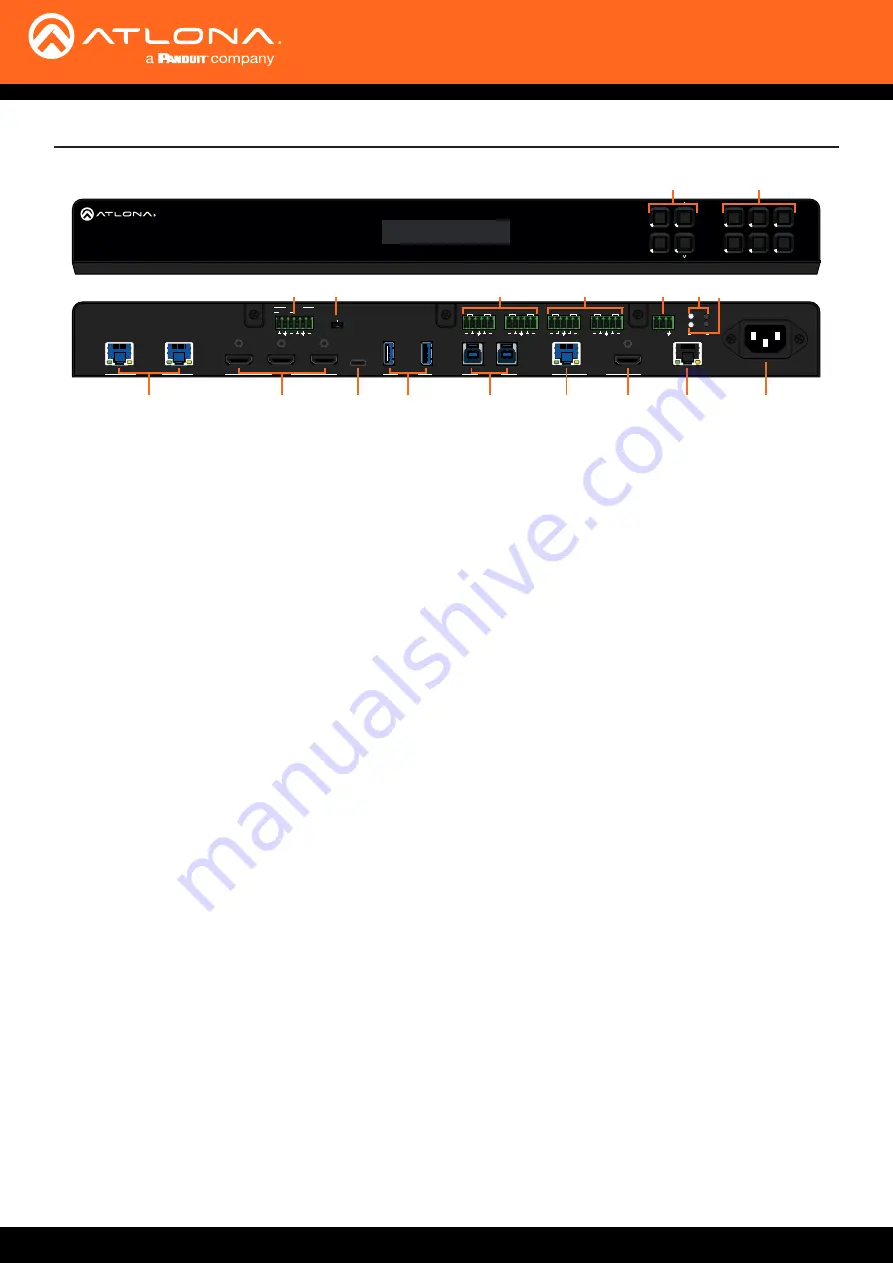
background image

AT-OME-PS62

9

Panel 

Description

ENTER

1

4

2

3

5

6

MENU

PRESENTATION SWITCHER

OMEGA

TM

PWR: 100-240VAC 50/60Hz  

RX TX

RS-232

IP MODE

RESET

1

2

1

2

1

5

3

4

2

LAN

6

USB-C IN

HOST USB

HDBaseT IN

HDMI IN

OUTPUT

USB HUB

MIC

48V

LINE

LINE IN

MIC

AUDIO OUT

R

L

1

R

L

2

R

L

2

AUDIO IN

R

L

1

AT-OME-PS62

10

14

13

11

12

17

15

16

18

1

2

5

3

7

8

9

4

6

1  Function Buttons 

MENU

 - Access the front panel menu or use as a 

back button within the menu. The menu can be used 

to route inputs, change audio and EDID settings, and 

view device information.


ENTER

 - Used for making selection within the front 

panel OSD.


^ and   

 - Use to navigate through the front panel 

menu.

2  Number Buttons


Use for selection of inputs and outputs.

3.  MIC/LINE input


Connect microphone or line input to this port.

4.  MIC/LINE dip switch


Use to switch between MIC, 48V, and line level input.

5.  AUDIO IN


Connect 2CH audio sources to these ports. 

6.  AUDIO OUT


Connect to an audio DSP, amplifier, or other audio 

distribution devices.

7.  RS-232


Use for device or display control.

8.  IP MODE LED and button


Press and hold the button for 5 seconds until the LED 

blinks to switch the IP mode between DHCP and 

Static IP modes. The LED will blink 4 times for DHCP 

and 2 times for static IP.

9.  RESET LED and button


Press and hold the button for 5 seconds until the unit 

resets. The LED will blink 3 times as the unit resets to 

factory default settings. 

10.  HDBaseT IN


Connect a compatible HDBaseT transmitter to this 

port.

11.  HDMI IN


Connect HDMI cables to these ports from HDMI 

sources.

12.  USB-C IN


Connect a USB-C source to this port.

13.  USB HUB


Connect USB devices to these ports.   

e.g.

 USB 

camera, mouse, etc.

14.  HOST USB


Connect to a computer using a USB B to USB A 

cable. USB 3.0 signal will only pass when using the 

local USB hub devices.

15.  HDBaseT Output


Connect a CAT5e/6/6a/7 cable from this port to an 

HDBaseT receiver.

16.  HDMI Output


Connect an HDMI cable from here to an HDMI 

display.

17.  LAN


Connect an Ethernet cable to this port for control of 

the unit or to pass Ethernet to a local device.

18.  100-240VAC 50/60Hz Power Port 


Connect the included IEC cord from this port to the 

wall for power.

^

Summary of Contents for Atlona Omega AT-OME-PS62

Page 1: ...AtlonaManuals Switchers AT OME PS62 4K UHD 6x2 Matrix Switcher for HDMI USB C and HDBaseT with USB...

Page 2: ...AT OME PS62 2 Version Release Date Notes 3 Nov 2023 Added notes for internal USB hubs in specification table Version Information...

Page 3: ...go to https atlona com registration Sales Marketing and Customer Support Welcome to Atlona Operating Notes IMPORTANT Visit https atlona com product at ome ps62 for the latest firmware updates and Use...

Page 4: ...purchase date for hardware electronics products purchased on or after June 1 2013 3 years from proof of purchase date for hardware electronics products purchased before June 1 2013 Lifetime Limited P...

Page 5: ...s or states do not allow the exclusion or limitation of relief special incidental consequential or indirect damages or the limitation of liability to specified amounts so the above limitations or excl...

Page 6: ...http patents dts com Manufactured under license from DTS Inc DTS the Symbol DTS and the Symbol together and Digital Surround are registered trademarks and or trademarks of DTS Inc in the United States...

Page 7: ...trol 15 CEC 15 RS 232 15 TCP Proxy 15 TCP IP 15 WebGUI 15 Front Panel Operation 16 Routing 16 Basic 16 ALL 16 Presets Save 17 Presets Recall 17 Audio 18 Route 18 Volume 18 EQ 19 MIC 19 MIC Ducking 20...

Page 8: ...sources and the optional Gain 60 or Gain 120 amplifiers purchasable through atlona com Introduction Features Package Contents Features two HDBaseT three HDMI and one USB C input USB C input for AV dat...

Page 9: ...evices 7 RS 232 Use for device or display control 8 IP MODE LED and button Press and hold the button for 5 seconds until the LED blinks to switch the IP mode between DHCP and Static IP modes The LED w...

Page 10: ...ANALOG IN L R Positive Positive Ground Connect dynamic or self powered microphones in this mode Use this setting for phantom powered microphones Supplies 48 volts Connect wireless microphone receivers...

Page 11: ...the case 2 Attach the included rack ears to each side of the AT OME PS62 using the case screws AT OME AT H DR H 2H 4 4M 1 2 3 4 RS 2 32 IR IN HDM I IN LAN FW DC 24V S RX TX OUT PUT 1 OUT PUT 2 OUT PUT...

Page 12: ...8 EN TE R 1 4 2 3 5 6 M EN U PR ES EN TA TI O N SW IT C H ER O M E G A TM Installation Refer to the tables below for recommended cabling when using Altona products with HDBaseT The green bars indicate...

Page 13: ...HDMI output port to a local display 11 Connect a compatible HDBaseT Receiver e g AT OME EX RX or AT OME SR21 to the HDBaseT output port 12 Connect the included IEC power cord from the power port to a...

Page 14: ...a s e T E t h e r n e t P o E H D M I U S B U S B C H D M I U S B H D M I H D M I U S B Gen eric SPEAKER SYSTEMS SPEAKER SYSTEMS Gen eric SPEAKER SYSTEMS SPEAKER SYSTEMS Gen eric SPEAKER SYSTEMS SPEAK...

Page 15: ...df This unit has the ability to translate IP data to RS 232 through ports 9000 This enables control of devices through TCP IP that only have RS 232 ports The unit will take the commands sent to port 9...

Page 16: ...r keys will be used Routing NOTE After 30 seconds of inactivity the front panel LCD will turn off Press any button to activate the LCD again ENTER 1 4 2 3 5 6 MENU Basic ALL Basic routing can be done...

Page 17: ...to 6 Select the memory number to save to and press enter 1 Select the MENU button 2 Use the and buttons to go through the menu options until the screen reads Route Setting 3 Press Enter 4 Use the and...

Page 18: ...ut options until the correct one is reached then press enter Use this option to select the audio source that will be routed to the analog audio output Use this option to adjust the volume of the audio...

Page 19: ...Select the output number and press enter 7 Use the and buttons to set the MIC routing on or off for the selected output Set the level of the EQ bands using these options EQ 1 Select the MENU button 2...

Page 20: ...ns to set the MIC ducking on or off for the selected output EDID EDIDs can be copied from the connected displays assigned to inputs or switched to one of the built in EDIDs to increase compatibility b...

Page 21: ...set the EDID mode for and press Enter Set EDID Mode EDIDs mode for each unit can be set between Default highest common resolution between the input and displays the previously saved EDID and Internal...

Page 22: ...Valens firmware IP mode IP address IP port SSH port MAC address and unit baud rate 1 Select the MENU button 2 Use the and buttons to go through the menu options until the screen reads Info 3 Press Ent...

Page 23: ...ress of the unit 3 Launch a web browser and enter the IP address in the address bar 4 The AT OME PS62 Register page will be displayed create a Username and Password 5 Write down the Username and Passw...

Page 24: ...e when Matrix mode is disabled Input Selection Manually route ports Only one port will be switchable when matrix mode is disabled When matrix mode is enabled it will have the option to switch both por...

Page 25: ...280x800 1360x768 1600x1200 1920x1200 2048x1080 1280x720p50 1280x720p60 1920x1080p24 1920x1080p25 1920x1080p50 1920x1080p60 default 3840x2160p24 3840x2160p25 3840x2160p30 3840x2160p50 3840x2160p60 4096...

Page 26: ...from a microphone Release Time Sets the delay time after no signal is detected that ducking stops Program Decrease Set the amount to ensure the program level is low enough when ducking is triggered th...

Page 27: ...to 10dB Mute Use the slider to mute and unmute the output audio Input Volume Level Adjustment Adjusts the input volume for each individual audio source Default is 0dB and can be adjusted from 90dB to...

Page 28: ...or off when detecting or losing A V signals Auto power off timer Sets the period of time between the loss of A V signal and when the display off command is sent Default is 15 seconds and can be adjus...

Page 29: ...urrent display is not found within the database use generic and manually adjust the command fields Repeat Command Enable Status to repeat the commands Default repeat number is 2 and can be adjusted fr...

Page 30: ...15200 8 None and 1 HDBaseT In 2 Select the baud rate data bit parity and stop bit that will be sent from the HDBaseT IN port to the connected HDBaseT transmitter This should be set to match the source...

Page 31: ...internal EDIDs and previously saved EDIDs EDID Saved The ID field will display the memory and currently saved EDID name select the output from the drop down menu to be saved Once the output is select...

Page 32: ...n be set to sync to a server as well Press the Sync button if using a server time or press the Save button if setting by timezone Daylight Savings Time Configuration Enable Disable slider Default is d...

Page 33: ...Add Select the Add button a new screen will open Enter a username and password then select Submit Up to three users can be added these users will not have the ability to see other other usernames and...

Page 34: ...econds Hostname Set the name for the matrix this will show up in network discovery USB Host Follow USB Sets the USB hosts to follow the most recently connected device If a host is connected then it wi...

Page 35: ...se the choose file button to search the local PC for the firmware file Once selected press the update button to start the firmware update Velocity Update For future update to the commands database whe...

Page 36: ...ol and configuration Bidirectional pass through from control system over HDBaseT Supported baud rates 2400 4800 9600 19200 38400 57600 115200 IP Protocols Https Telnet mDNS Modes DHCP Static selectabl...

Page 37: ...pin female HDBaseT OUT 2 1 RJ45 female USB HUB 2 Type A 4 pin female USB HOST 2 Type B female LINE MIC IN 1 6 pin captive screw balanced unbalanced line level input w 3 pin MIC option LINE MIC Switch...

Page 38: ...Toll free US International atlona com 877 536 3976 41 43 508 4321 35116 R3...

Reviews: